Cylinder Head removal part2 – Success

Cylinder Head removal part2 – Success

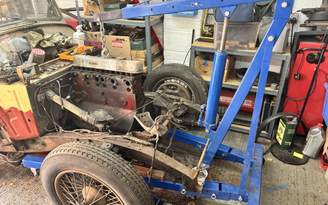
I awoke this morning with a bit of a Eureka moment concerning the removal of the head. In my waking moments it occurred to me that perhaps I might not need to remove the valve push rods because if the hole they went through had sufficient clearance then they would pass straight through when I lifted the cylinder head up. I had removed 4 of the 12 push rods because the service manual implied that I needed to remove them all - so I simply tried inserting one of the removed push rods (upside down) into the hole and I am very happy to report that they had loads of clearance so I removed the tool I had made as I clearly didnt need to continue with removing them all at this time.

It was at that moment that I noticed the front of the cylinder head had lifted up a couple of mm but the back was still firmly against the engine block so it occured to me that perhaps my engine crane was NOT lifting the head vertically. So I adjusted the handle of the engine stabiliser so that the crane now lifted the rear of the engine slightly more than the front. This lifted the head (slightly) at the rear but the front had dropped down. This was great news and was rather exciting because it meant that in theory the head WOULD lift up if I adjusted the engine stabiliser just-so.

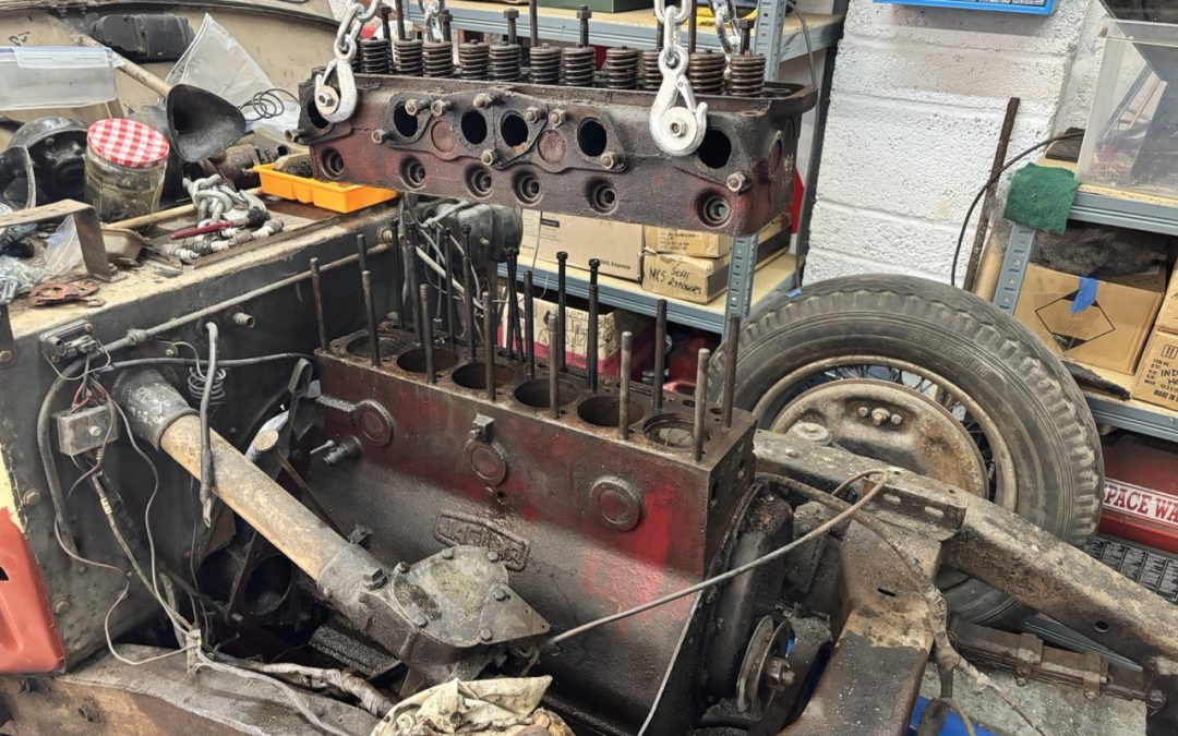
With a little more adustment and additional lift applied to the crane hydraulic ram the head moved up evenly a couple of millimeters. Excitement was high now so I continued to raise the crane and the head slid happily up the studs and OFF the engine! I was overjoyed and I just had to share this moment of success with my ever patient wife who strangely was not quite as entusiastic as I was šŸ™‚

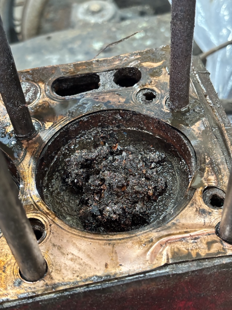
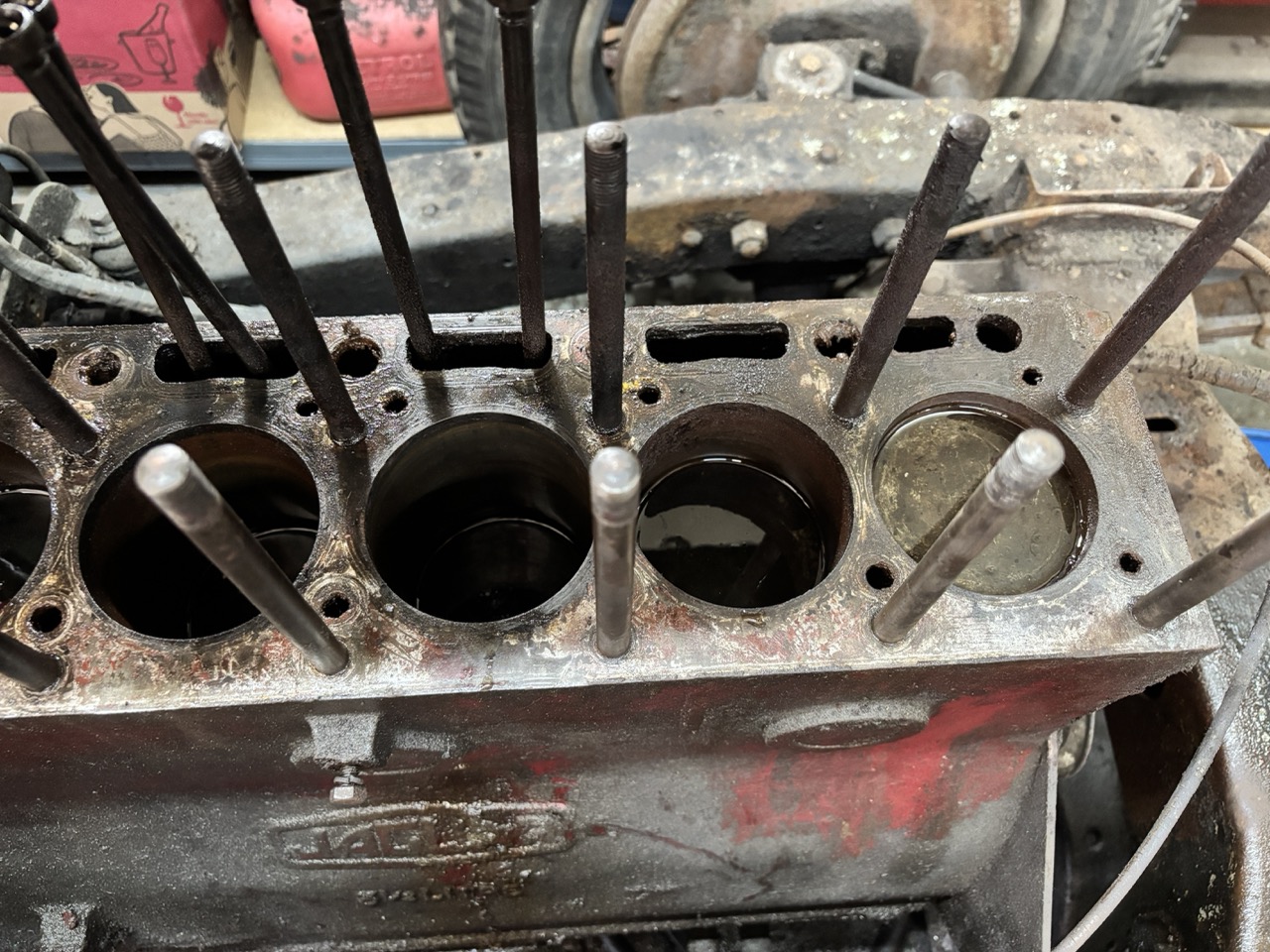
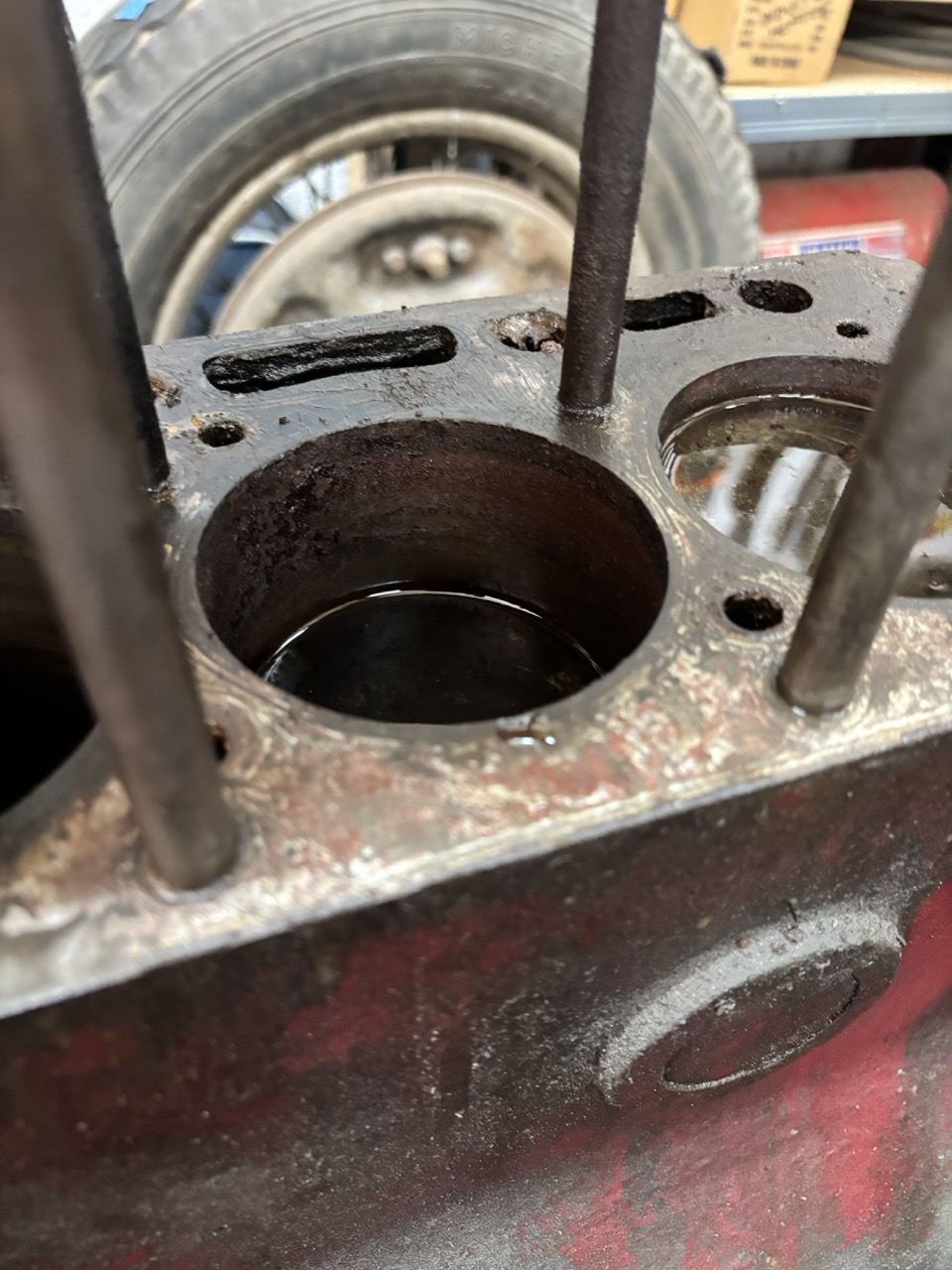
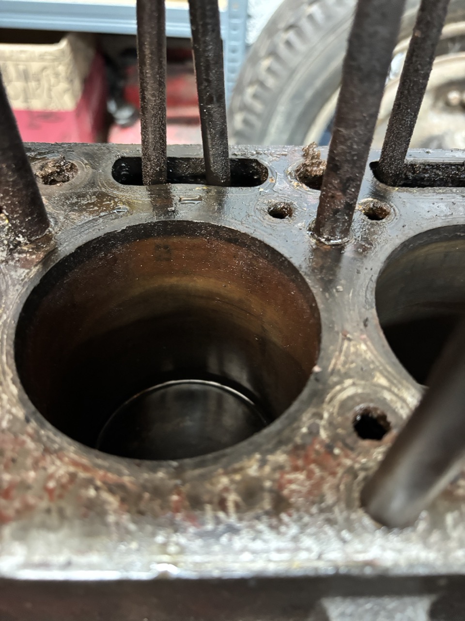
I could now take my first look inside the engine and noticed that all of the bores were still full of diesel, which I had poured into them in the hope that it would soak into the rust and free up the pistons. If it did do anything then it wasn't a total success because I would image some of the diesel would have found its way into the sump. So I removed most of the liquid so that I could take my first look at the cylinder bores. I was greeted with seeing sludge as you can see in the photo above. This was a thick sediment that wiped off the top of the piston revealing corrosion around the edge of the piston. The other cylinders were about the same - the bores are clearly pretty rusty so I will need to clean out all the rust I can see before trying to remove the pistons.

The exciting part is of course that the cylinder head is now off and I can move onto the next steps of trying to release the pistons. My thanks go to the learned people on the Jaguar Lovers Forum for suggesting the use of an engine crane to release the head.

Cylinder Head removal

Cylinder Head removal

I was not expecting the removal of the cylinder head to be easy. it has after all been sitting undisturbed for around 40 years. But what I was not expecting is to struggle to find somewhere to grip in order to pull the cylinder head up & off the studs. The Jaguar Lovers Forum (Link to Website) was helpful as usual with a number of suggestions as some people mentioned that if the studs have rusted then it can be a real pig to remove it.

My chosen option was to initially pour rust dissolving fluid down the 'stud holes' and leave it for a week or so. THEN use mechanical power over human strength - i.e. lift the cylinder head using an engine crane. I have a good, heavy duty engine crane but it is big and consumes a lot of garage space when it is in the 'use-me' mode and I feared that it may not go underneath the car. I was partly correct in my fears because the legs are mounted on quite large wheels and they hit the engine cross member - but only just. My plan therefore was to use a small car-jack to lift the front of the car around 5mm. This worked a treat and the engine hoist rolled under the car. At which point I lowered the car back down. I then extended the engine hoist arm so that the end of it was around the middle of the engine. In that configuration - the engine hoist is capable of lifting 1.5tonnes which is hugely above the weight of the engine so I had no fears of doing this.
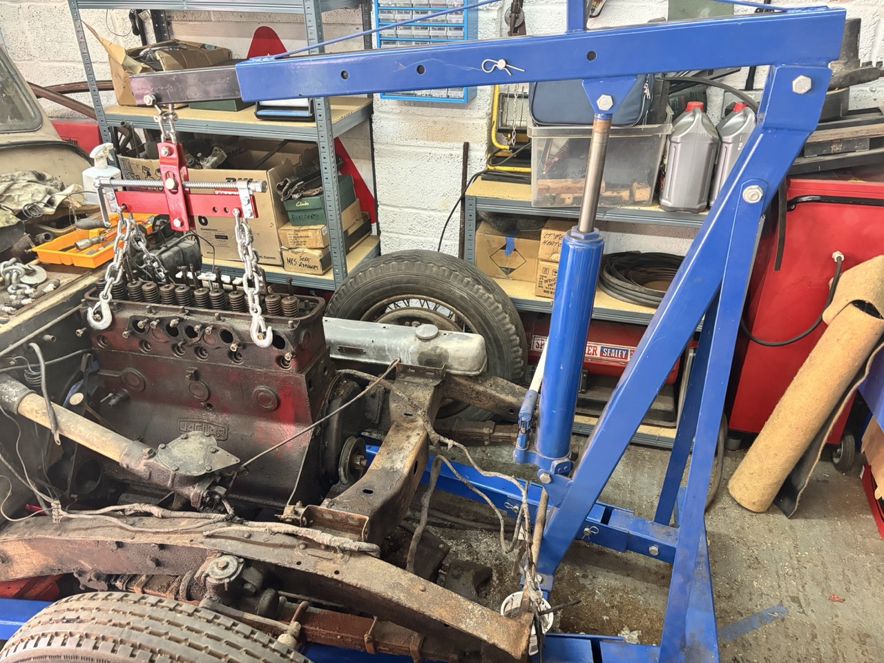
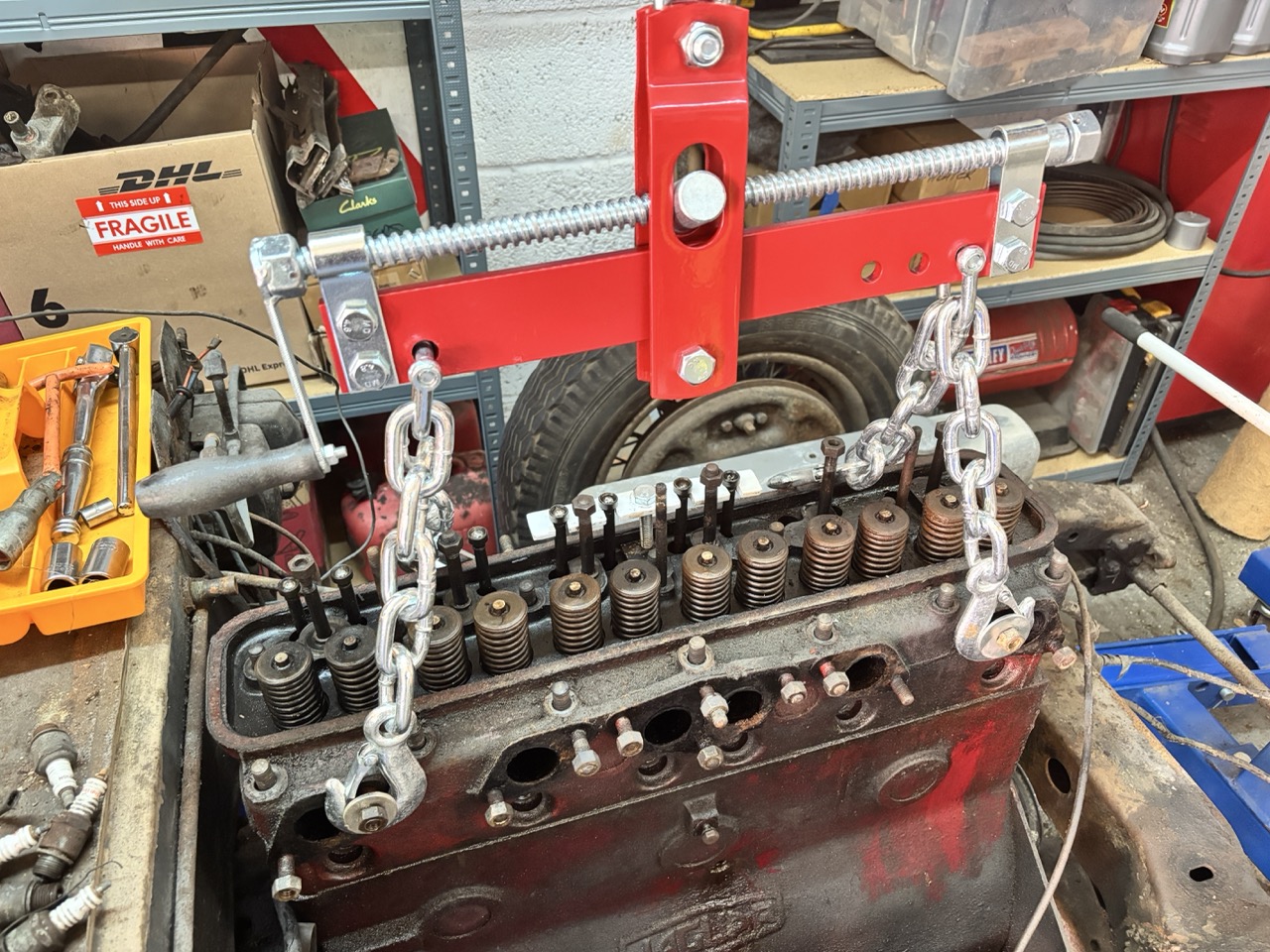
Next I replaced the 'hook' with an engine stabiliser so that I had four hooks that I could connect to the engine to pulll upwards evenly. In the photo below the stabilizer is loosely placed so that I could work out the best place to fit the hooks. In the end I chose the exhaust studs on one side and the inlet studs on the other side. Obviously the hooks need to be secured so this was done simply by placing a large washer on the end of the studs which prevents the hooks sliding off. Simples.


The engine hoist is then raised slightly which applies an upward force to the cylinder head. It actually lifted the front of the car slightly so I KNOW there is a pulling force applied so it is now a waiting game, pouring more rust dissolver Ā down the studs, giving the head an occasional whack with a hammer and we will see what happens.

And a few more woes

And a few more woes

My plan is to remove the head and take a look at the state of the pistons before doing anything else on the car - basically the value of classic cars has fallen massively over the last couple of years and if the engine is beyond restoration - then sadly so is the car because these engines are pretty rare. But if I CAN get the engine to move then the restoration is more about building a car that I can enjoy for many years than it being economically viable. So with that sad comment behind me, let’s crack on.

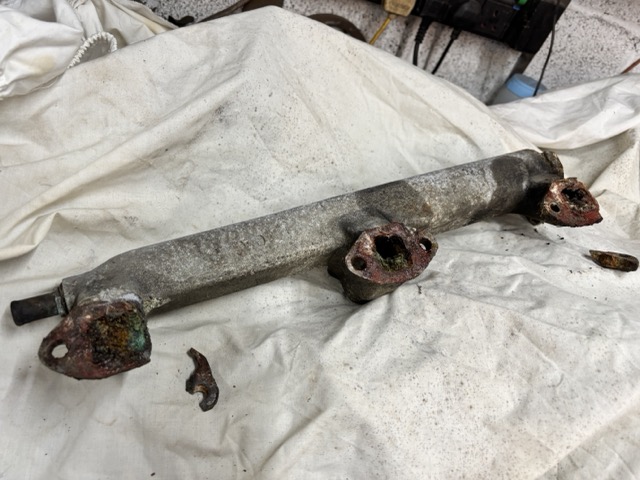
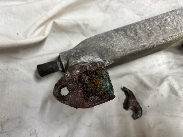
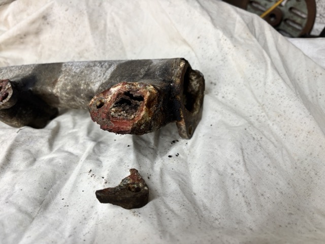
First item to be removed is an alloy casting that ports hot water from the cylinder head to the radiator - a pretty important job. Sadly as mentioned in the previous post, it has a significant crack where it bolts to the thermostat housing. Upon removal and as you can see in the picture above - the casting has other issues in that 2 of the lugs where it bolts to the cylinder head were severley corroded and they just fell apart. INSIDE the casing, the water ways were gummed up with corroded alloy. I have seen this before - when alloy encounters extended periods of moisture in the air - it swells and crystallizes. It is removable but that will still leave the issue of the broken mounting lugs

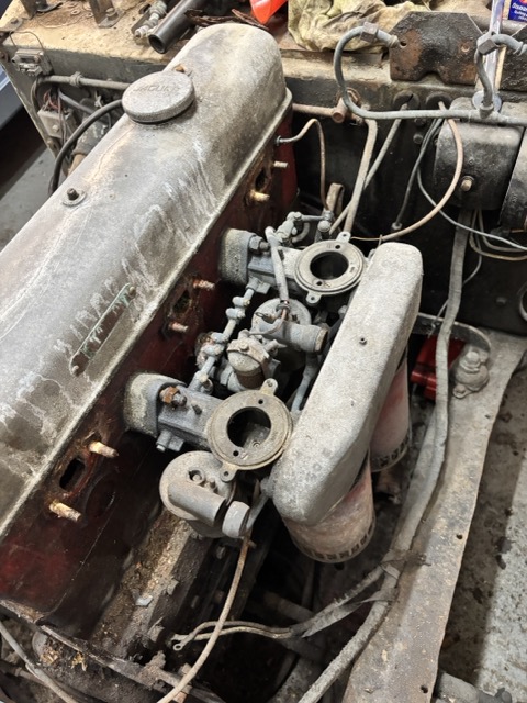
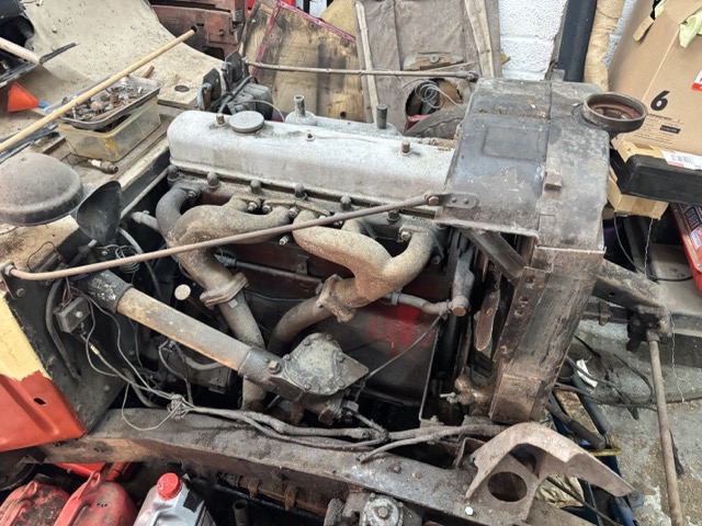
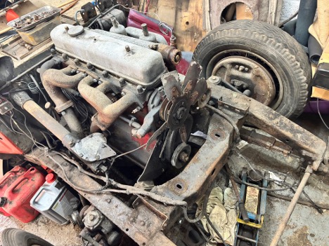
With the casting removed, I can get to the carburetor mounting bolts and as you can see in the picture below; there are 2 carburetors and they are bolted directly onto the cylinder head. This was a prewar design that was later superseded when people discovered that that the speed of the fuel/air mixture into the cylinders made quite a difference to the performance of the engine and so ā€˜inlet manifolds’ were developed. Between the 2 carburetors is actually a third carb - it is an ā€˜automatic enrichment device’ or AED. It’s basically an electrical choke used when the car needs to be started from cold and it automatically switches off when the engine no longer needs additional fuel to run.

I chose to remove the entire carburettor/AED/linkiages and air filters as one unit but was disappointed to see that one of the carburetors is broken where the AED bolts on. I am guessing that something heavy landed on this area when the car was in storage but the damage could not be seen whilst they were in place. Luckily, the carburetor is replaceable and would have been rebuilt anyway but this is another item on the ā€˜Woe list’.

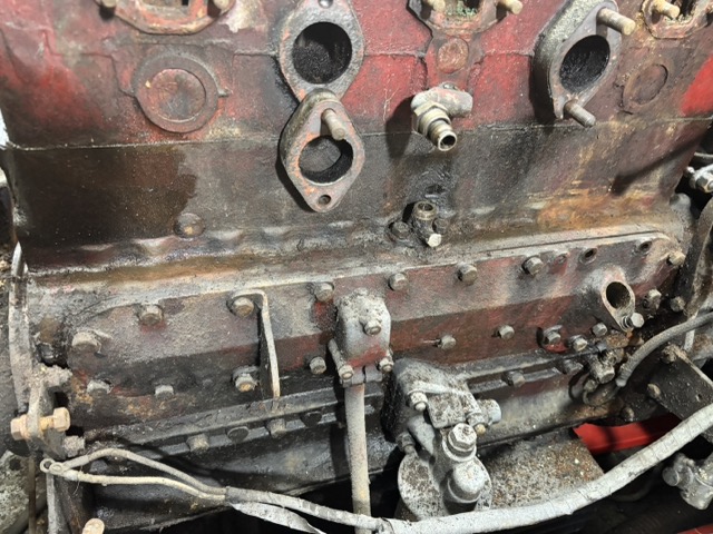
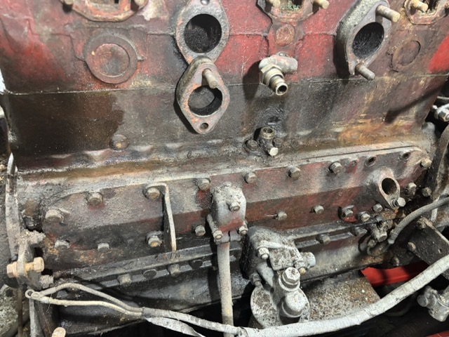
With the carburetors removed that side of the engine block now looks like this:

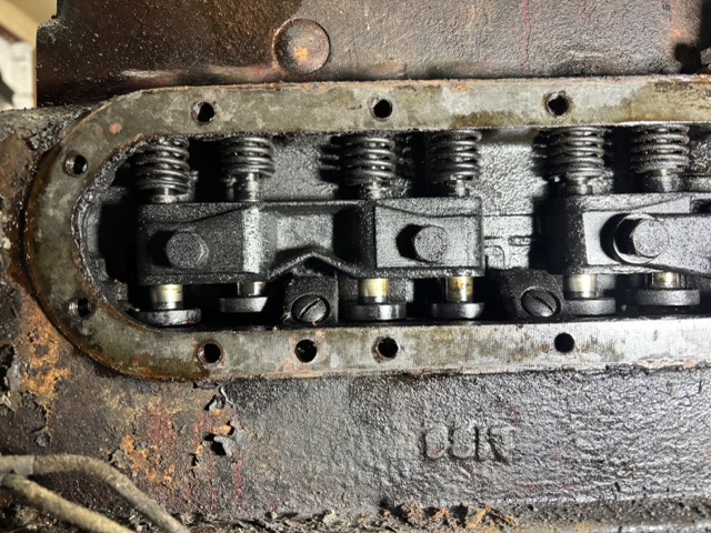
I thought this would be enough of a strip down to enable me to unbolt the cylinder head and the picture below shows the shaft that pushes down on the valves to let fuel in / exhaust gasses out. This is called the ā€˜rocker shaft’. The valves are above the pistons which makes this style of engine an OHV - ā€˜Over Head Valve’. Inside the depths of the engine is a camshaft which has one eccentric lobe per valve. As that shaft rotates the lobe pushes up a rod (yep called a push rod) which in turn lifts one side of the rocker which in moving pushes the associated valve DOWN. Strong springs return the valve to its resting place when the lobe of the camshaft is rotated back to zero lift. Pretty simple mechanics really, Fun to rebuild because it *IS* so basic. No electronics or computers needed here.
Ā removed the rocker shaft and put it to one side for cleaning at a later date. It is here that my experience told me that the push rods should simply slide upwards out of the cylinder head. To my surprise none of them were interested in being lifted up. They were not seized, it merely felt like something was holding them in place which based on my experience is definitely not ’normal’.Ā 
So it was onto the Interweb thingy to ask learned people in a Jaguar Forum I stumbled across a couple of years ago. A few people said ’they just lift out’. Well, yeah-no, actually they dont… then a helpful chappie sent me a picture that showed the bottom of the pushrod having a spring that is mounted between the underside of the cylinder head and the bottom of the pushrod which pushes said rod down onto the camshaft lobe… so I now had to work out HOW to remove those springs which I could not yet see...

Said learned chappie told me that below the carburetors is a substancial metal plate that the distributor is mounted onto. Substantial was not an overstatement. It is approximately 10mm thick steel...

To remove that plate - I needed to remove the distributor and THAT…. was seized in place and required copious amounts of anti-seize fluid before it was interested in moving. Once it was rotating in its mount, it STILL wouldn’t come out because what you could not see below the distributor was a small bolt that went into a slot in the distributor shaft to prevent the thing coming out…
It is at times like this that events force you to display your inner character. However the joys of beating the problem outweigh the frustrations (usually). Distributor off. Substantial plate off.
With the plate removed I can see that for a set of 4 pushrods there is a thick metal block that houses 4 cam followers (the part that sits between the pushrod and the camshaft. But you cant remove that block (to remove the pushrod springs) because all the springs are under tension…

It was at this moment that I thought ā€˜perhaps the service manual’ has some guidance. 'Service Manual' is definitely an overstatement, it’s more of a Service Pamphlet. A thin paper back book (perhaps 7-8mm thick) that is supposed to tell you how to service EVERYTHING in the car, including how to strip down the engine. So I read the short paragraph that mentions the pushrods. It said ā€˜Use the tool in section O to remove the pushrods'.

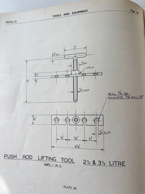
So with a level of excitement I looked at section O. I found this:

A ā€˜Pushrod lifting tool’. But no clues on how to use it, where to place it, how it functions…
Much head scratching followed. Obviously I dont have that tool, but the reason Jaguar kindly supply drawings like this is to enable mechanics to make one. That’s fine, I can indeed make one - but how is it used?
I asked the forum again but sadly no-one had any ideas, apart from one chap who said it goes under the push rods and lifts them. Thanks for that… Other people chipped in and said they never used one but they didn’t say how they got past this stage. Then one night - I awoke and had a Eureka moment - perhaps the tool went on the TOP of the cylinder head and when that central ’T’ shaped part in the drawing was rotated, the plate would raise up to the shoulder of the cup at the top of the pushrod and it would then lift all 4 of the Pushrods away from the Cam follower block. Now this was an exciting moment and I spent a happy 30 minutes in my workshop fabricating ’the tool in section O’.
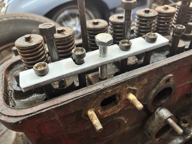
Below you can see it in place and yes it does indeed lift all 4 of the push rods away from the cam follower block.Ā 

Huzzah.... onwards

A few more woes

A few more woes

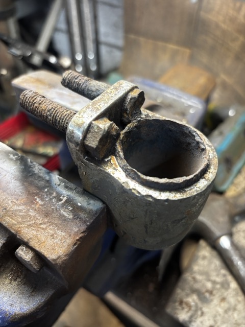
Progress is definitely happening—mostly in small but satisfying steps—and with every step I uncover yet another little surprise that’ll need attention later. For example, the bumper‑mounting shaft appears to have broken right through the casting that’s riveted to the chassis, so it no longer screws in as it should. I suspect this bit of drama occurred during the accident that saw the car taken off the road. The bumper itself has a slight kink too, and since it’s made from very thick spring steel, I’m not sure it can be persuaded back into shape without a fight.

The engine, meanwhile, remains thoroughly seized and is going to need some… persuasive encouragement. The central hinge on the bonnet has also called it quits at one end and will need replacing. One side of the rear bodywork has slumped by just over a centimetre. I’ll have to sort that before I even think about welding the sills in. There’s still loads of bodywork ahead, and both of the enormous headlights have earned themselves noticeable dents. But the real star of the show—the elephant in the garage - is that seized engine. Thankfully, I’ve tracked down an engine specialist who’s rebuilt over a hundred of these pre‑XK units… but first, I need to get mine unstuck!Ā 

This engine is essentially the same as the one used in the SS100 sports car: a twin‑carb, 3.5‑litre overhead valve setup. One known weak spot is Jaguar’s brief experiment with lightweight alloy conrods. They turned out to be rather brittle, with a tendency to let go at high speed, which is not an experience I’d like to have. Luckily, I managed to find a set of steel conrods that will replace them. As a charming pre‑war quirk, the carburettors bolt straight onto the cylinder head—no inlet manifold in sight!

Onto my attempt(s) to unseize the engine.
To tackle the seized engine, I’ve had the pistons soaking in diesel for months. Diesel is basically thin oil and doesn’t evaporate, so in theory it should creep into the rust and ease its grip. The car still has its original starting handle, whichĀ shouldĀ help rotate the engine, but so far it remains as willing as a cat at bathtime. Time for stronger persuasion.

One method is to remove the starter motor to gain access to the flywheel teeth, then apply a suitable lever (read: crowbar) and see if anything is willing to move. So, off came the bonnet—which is how I discovered the hinge issue—and then the radiator, which must have been carved out of solid brass because it weighs a ton . Once those were out of the way, I finally had the space to get at the starter.

This sounded simple enough—three bolts and one hefty cable—but one of those bolts also serves as a brake‑pedal return stop/adjuster, which meant it wasn’t keen to leave its cosy home.

After some fiddling, I freed the bolts and cable… only to find the exhaust downpipe blocking the motors’ escape route. As the entire exhaust will be replaced anyway, I cut the downpipes just below the manifold, and at last the starter motor came out.

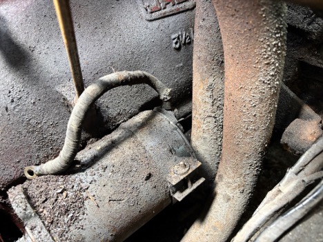
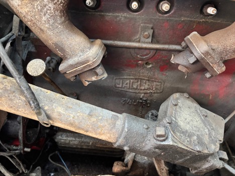
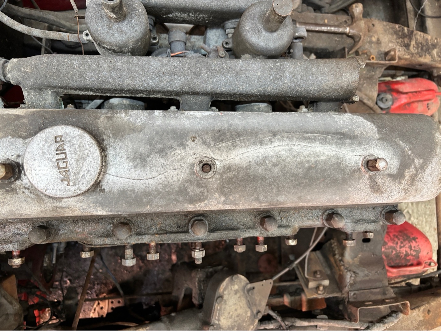
That’s when I spotted a new mystery: a 1.5cm hole which can be seen just above the Jaguar logo on the block. According to fellow SS and Mk4 owners, that hole definitely shouldn’t be there. One theory is that someone drilled it to relocate the block’s drainage tap—which Jaguar originally placed in a rather silly spot above the starter. The coolant is not pressurised, so plugging the hole will be easy enough, but I’m keen to find out why it’s there in the first place.

With the starter finally removed, I tried levering the flywheel to see whether the engine would budge—an exciting moment that lasted all of three seconds. Nothing moved. Not even a polite wobble. Which means the next step will be removing the cylinder head to see just how stubborn things really are… but that’s a story for the next update.

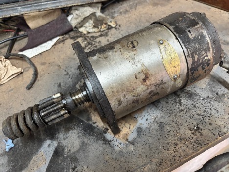
On a brighter note, I did enjoy finding a brass plaque on the starter motor. These little touches add real charm to what is otherwise a very utilitarian component. I haven’t tested the motor yet, but it does rotate, so with luck it’ll be perfectly restorable.

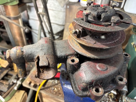
Whilst I was ā€œin the neighbourhood,ā€ so to speak, I decided to remove the water pump—after a brief mental challenge of trying to figure out how it was actually attached. My reward for this triumph? Yet another entry for the ever‑expanding List of Mechanical Miseries: the casting is cracked right where the main hose connects. Can these castings be repaired? I’ve no idea. The pump itself is internally corroded, stiff as a Victorian butler, and generally unenthusiastic about turning, so I’ll see if I can coax some rotation back into it before I start begging the world for replacement parts.

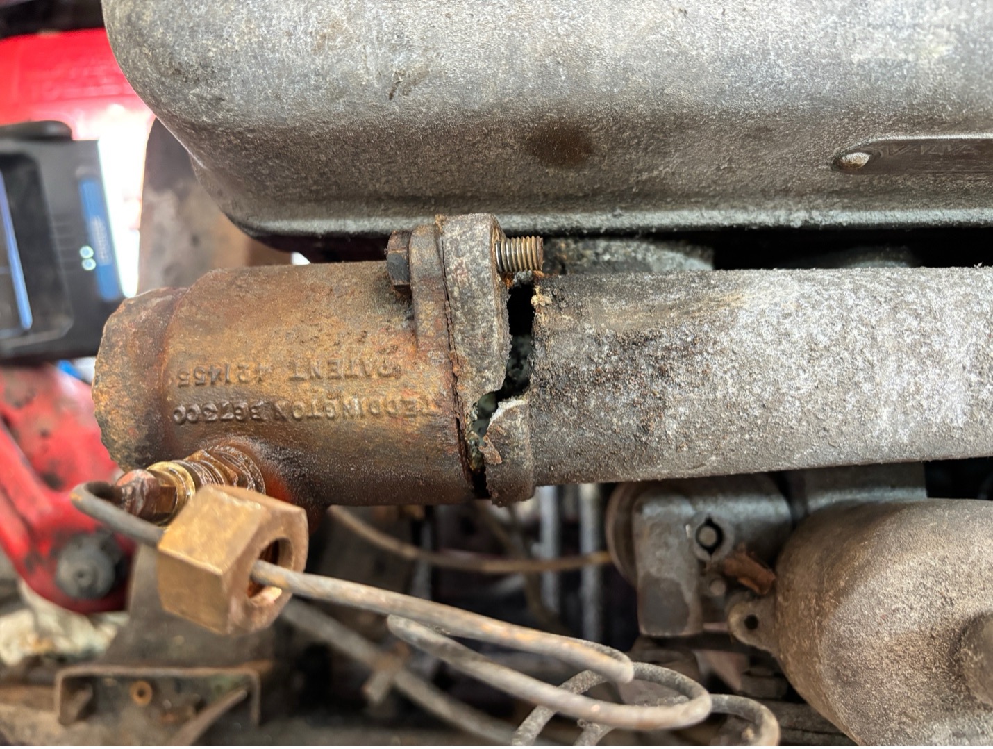
On to the next delight. Removing the thermostat housing (which also holds the temperature sensor) revealed that the aluminium casing/water jacket had suffered a break at some point in its life. Judging by the colour of the fracture, it’s an old wound. Perhaps it can be laser welded, assuming the welder doesn’t laugh me out of the workshop.

Speaking of laser welding, the valve cover decided to join the List of Mechanical Miseries by showing me it has a long stress crack running between the bolt holes. Apparently this is quite common and usually caused by someone in the past over tightening the bolts. Modern practice, I’m told, is to laser weld the cracks and polish the repair until it’s invisible—though I imagine one must still take care not to warp the casing and create troublesome oil leaks.

I’ve no doubt there are more surprises lurking in the shadows. This was always destined to be a challenging restoration. But the true project killer will be an engine that refuses to un-seize… and for that cliffhanger, you’ll have to wait for the next update to see whether I triumphed or sat in the corner sulking...

Front Bumper woes

Front Bumper woes

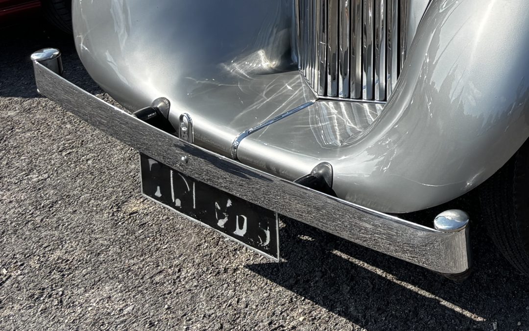
As you can see in the picture above, prewar bumpers are slim and elegant, on first sight they simply look like a flat piece of steel with a graceful loop on each end, finished off with a polished cap. In reality they are very substancial, behind them are 3 spring steel leaves rather like suspension leaf springs, and those nicely rounded ends - are full of lead.

The spring blades were designed to dampen vibration in the bumper blade but they also absorb impact during low-speed collisions. Their flexibility allowed the bumper to bend rather than break, providing a better safety feature for both the car and the occupants. The spring mechanism also (in theory) enabled the bumper to return to its original shape after being deformed, which added longevity to the bumper structure.

Filling the ends of bumpers with lead served to balance the weight of the bumper, providing more stability. This allowed for a smoother drive and improved the overall aesthetics of the car. All of this means that elegant looking thin bumper blade is flipping heavy!

You may recall I had mentioned the previous owner had an accident in the car many years ago (which wrote off the midwives vehicle) but the crash impact left a slight kink in the bumper blade which may or may not be 'repairable'. That is something for another day though. Today Ā I wanted to dismantle the bumper to ascertain whether the bumper mounts (which will need to be re-chromed someday) are salvageable as they are severely rusty.

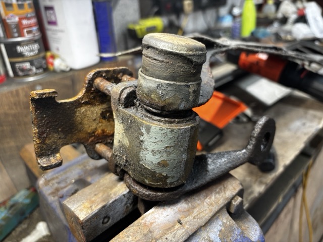
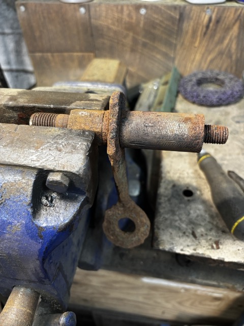
The bumper mount is essentially a length of bar about 150mm long that is screwed into the chassis. Onto that is slid a mentalistic bush which fits inside a brass housing with four bolts allowing a securing plate to clamp around the spring blades. Also fitted onto that mounting bar is a separate bracket for fitting the spot lights. Sadly all those components are rusted solid into one big lump. The bar itself, I can remanufacture - but I need to keep the bumper mounting bracket... therein lies todays fun - getting all of that apart so it can be restored and refitted another day.

Undoing the four nuts was not too difficult - I have an induction heater that when placed over the nut, rapidly heats it to red hot. If you then rapidly cool the nut, then reheat it again - more often than not the rust in the threads releases and the nut can simply be undone with a spanner. This saves a lot of anguish and the localized heat does not affect any other areas.Ā 

Above you can see the removed entire bumper mount. The top item is simply a rubber block pushed into a sleeve which apparently is there to further reduce vibrations but is easy to remove - below that is a nut that holds the whole mount together. As that nut is protected from the elements, it too was easy to remove. That is where 'easy' stopped. The rest of the mount is fused together with rust and despite soaking in rust remover for several weeks, nothing will budge.

Sadly I didn't photograph the mounting with out the top elements. But I needed to remove the perished metalsatic bush so that I could remove the bolts you can see in the picture above. breaking apart an ancient rubber bush is relatively easy using a power drill and eating through the rubber until basically all of it is removed. The main bar can now be removed leaving part of the bush in the mount and the inside part of the bush on the bar. Next step is to remove that bush outer sleeve from the mounting. A saw cut down the length of the sleeve is a tried and trusted method of releasing the grip slightly so the remains can be 'persuaded' to come out. Next the more challenging part....


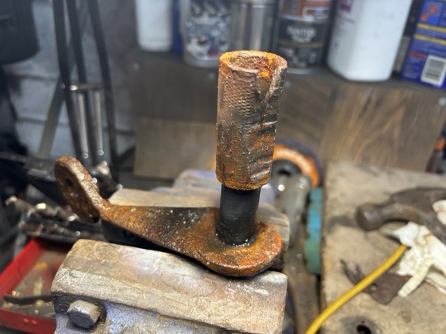
Above you can see the inner mounting bar with the bracket that supports the spotlight. In theory the tube (which is the inner sleeve of the mentalistic bush) should slide off the bar... hmm... that will be a firm 'no way'. Several weeks more soaking with penetrating fluid achieved nothing. I couldn't put the whole thing in my lathe because the bracket would hit the lathe bed so I chose to try and gently cut the sleeve from right to left along with applying MUCH heat-cooling. Eventually I ended up loosening it.

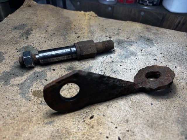
And then wriggling the bracket free of the bar.

I cleaned the bar up on the lathe and it can now be reused. The spotlight bracket is very coroded (and is not available to purchase) so I may end remaking that...

Can I buy a replacement melastic bush? Not so far... but I have been investigating 3D printing of a rubber-like material that people use for vibration damping so perhaps... I can MAKE a replacement bush of the correct size.

When people ask ' why is the restoration going so slowly... I will point them to this blog entry šŸ™‚