Door Hinge

Door Hinge

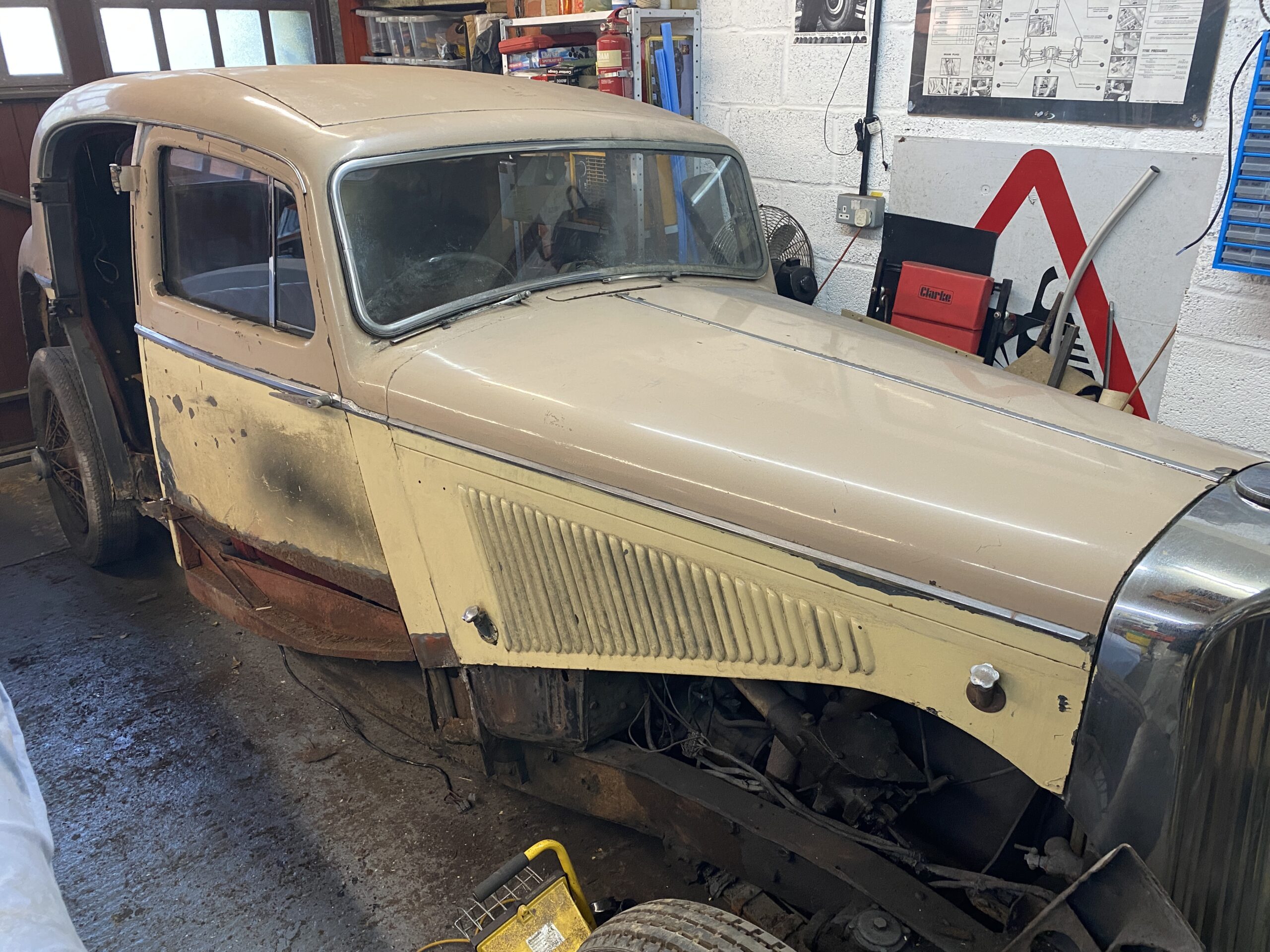
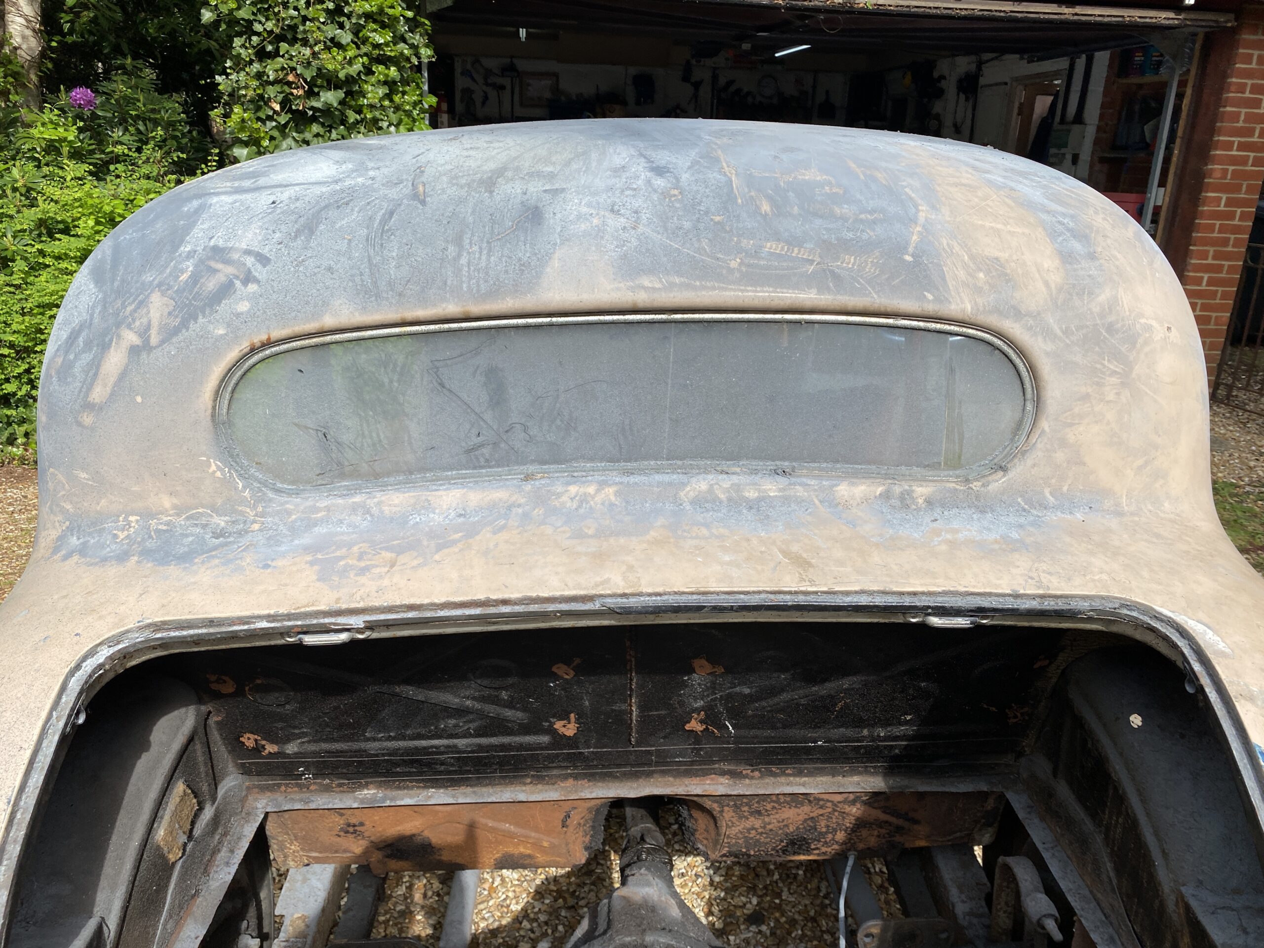
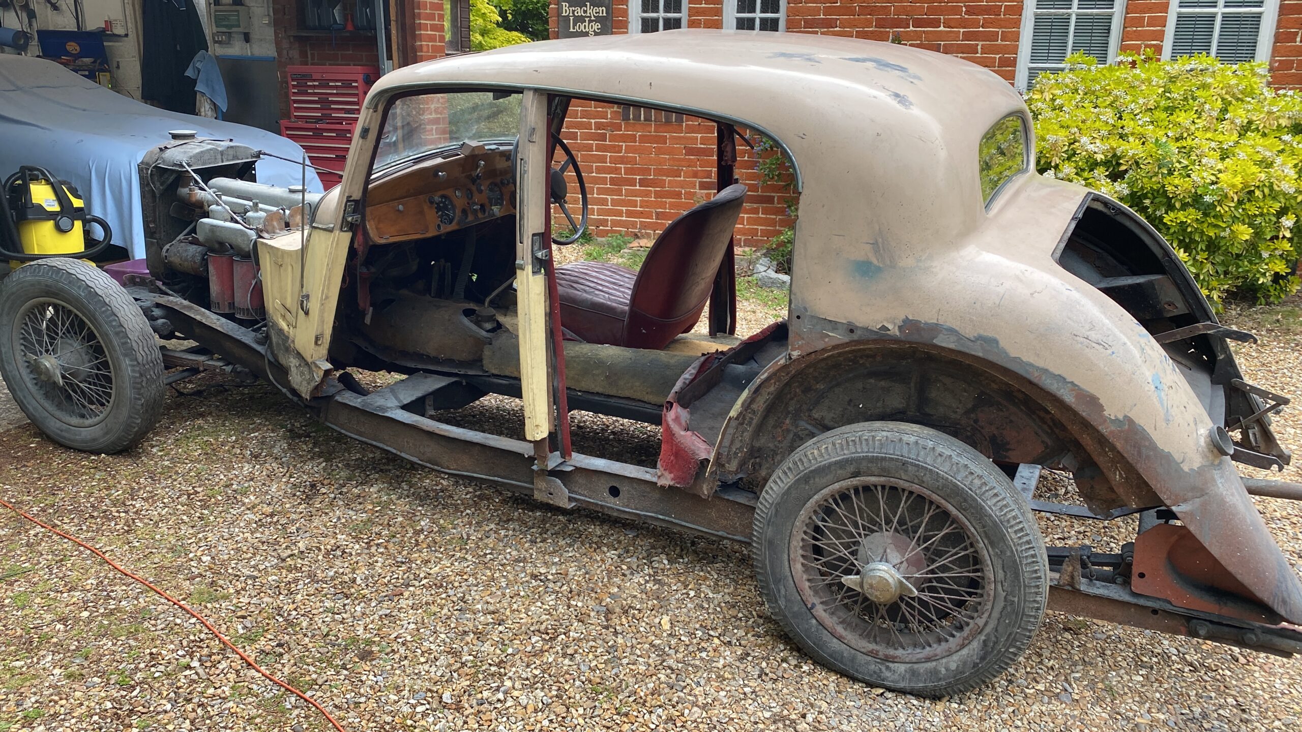
I had not really intend to fit the doors until much later, but I needed to know where the inside edges were to ensure that when I weld in the rocker panels (door sills) the door does not hit them and *not* close. So I thought I could fit the door, take a few measurements and then crack on with the rocker panel.

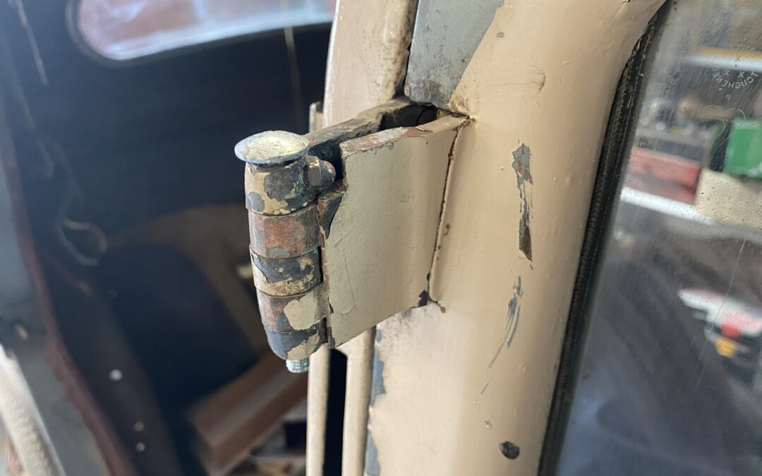
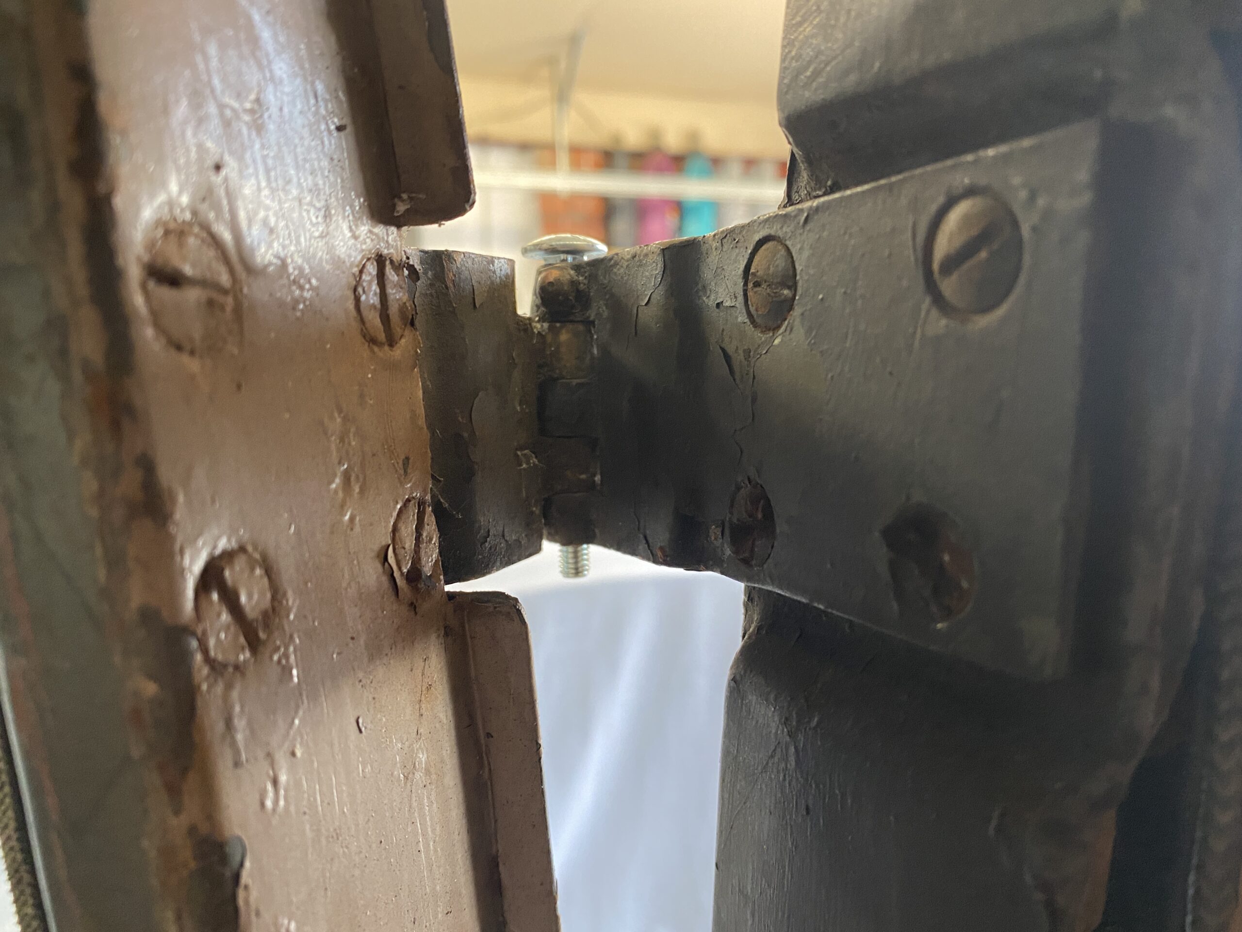
It was at this point that I discovered that the hinge pins had been sawn through rather than removing the hinge screws. I wondered why this was done so I tried to undo the hinge screws - yep they are seized. I think I would have drilled out the screws rather than saw through the hinges but we are where we are. Unfortunately this left the remains of the steel hinge pins in the brass hinges and you cant hammer out the remains because the soft brass would bend. Heating the hinge to release the remains of the pin did work on one piece - but not on any of the others, so I was back to having to remove the hinges from the door & door post so that I could drill out the remains of the hinge pin.

The old school trick of heating seized components to break the corrosion grip loosened 3 of the 4 screws leaving me with one to drill out. This has to be done carefully and patiently so the drill does not remove the thread from the back plate. Once removed the hinges were clamped vertically in the drill press and the pin remains drilled out.

I will need to tidy up saw marks from the hinge so they can be re-used (I dont appear to be able to buy new hinges) and I will need to manufacture new hinge pins (I cant buy those either) but temporarily a 6mm bolt is slightly too small so the hinge has free play that should not be there, but it is good enough for me to fit the door and see where the rocker panel needs to go.

Needless to say, this took a LOT longer than it took to write this - a couple of weeks, but the drivers door is now in position. What surprised me is the panel gaps around the door are tiny - about 1mm. On a modern car they are more like 3-6mm. Coach-building standards were quite impressive back then.
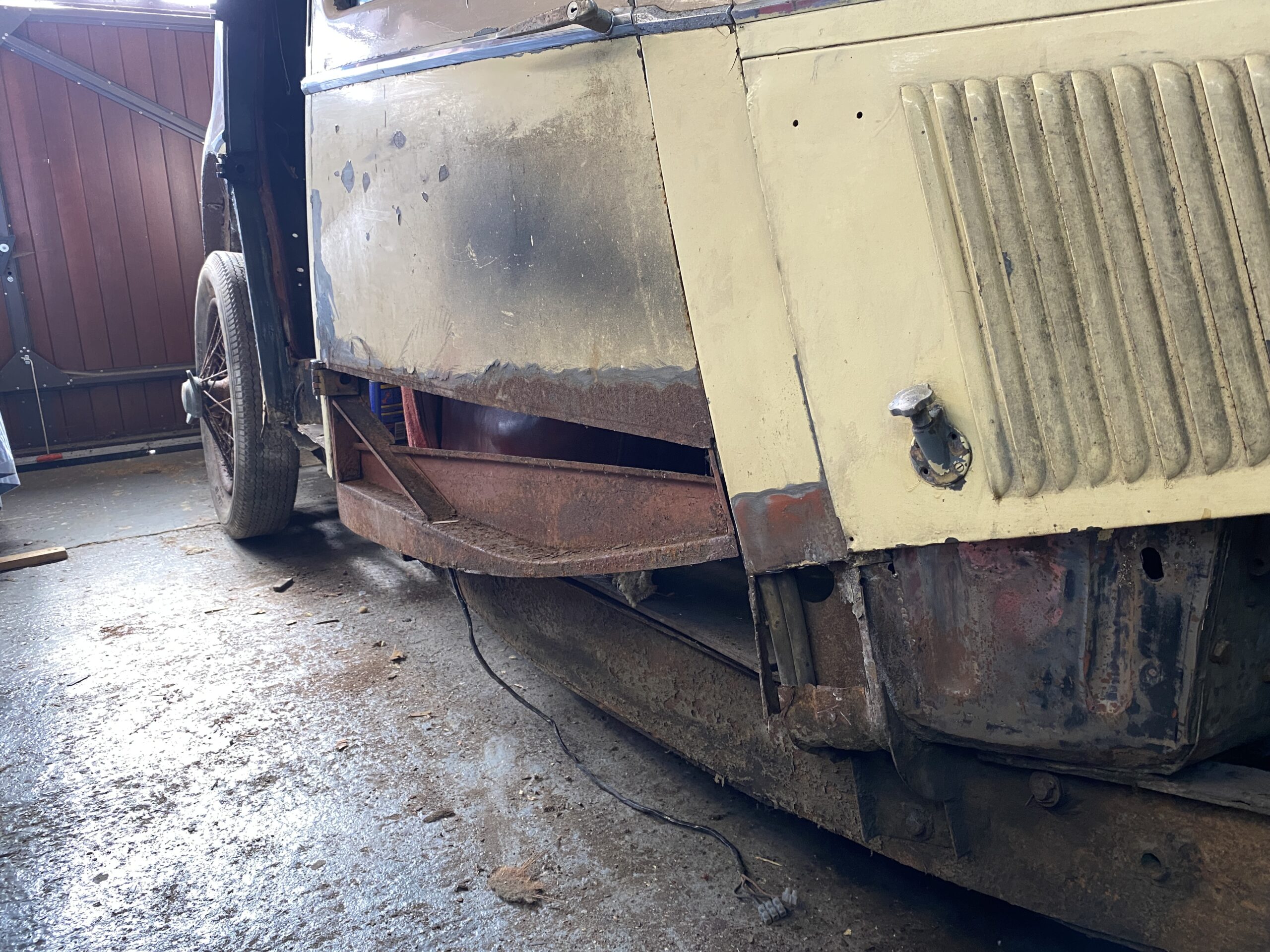
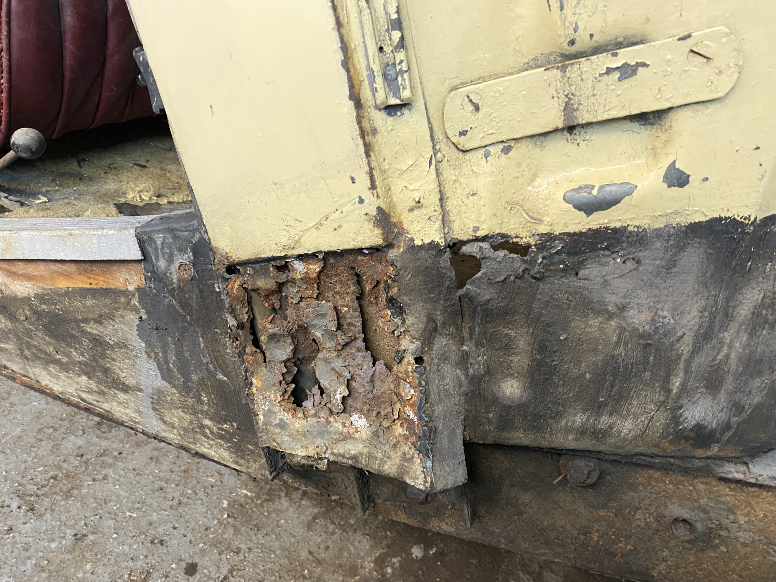
Now I can see where the bottom of the door is - I can work out where to fit the Rocker Panel so that it misses. Repairing the door skin is definitely not a priority on the job list. But it was fun freeing up the door locks, window winder and the quaint quarter light window that opens with a rotary handle. I was rather pleased to find the door closes under its own weight - which is very classy indeed.

Metalwork Part 2 – Drivers Footwell

Metalwork Part 2 – Drivers Footwell

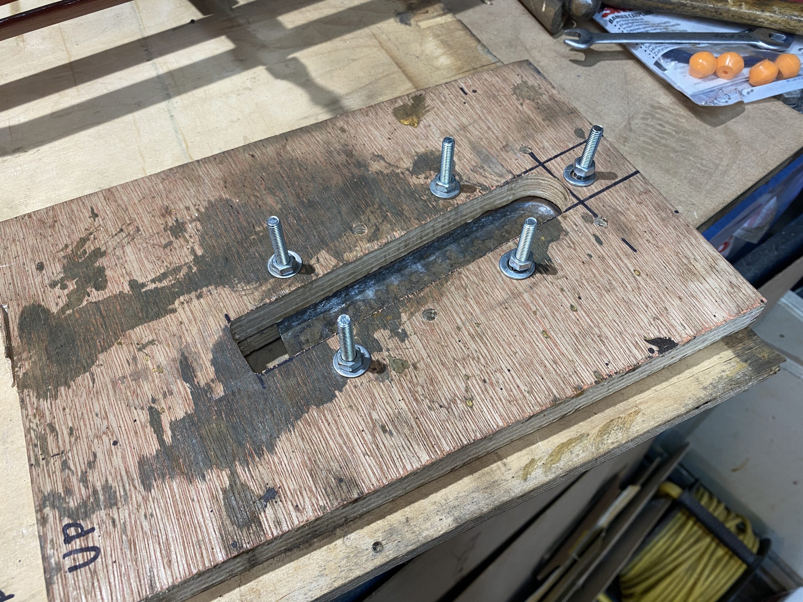
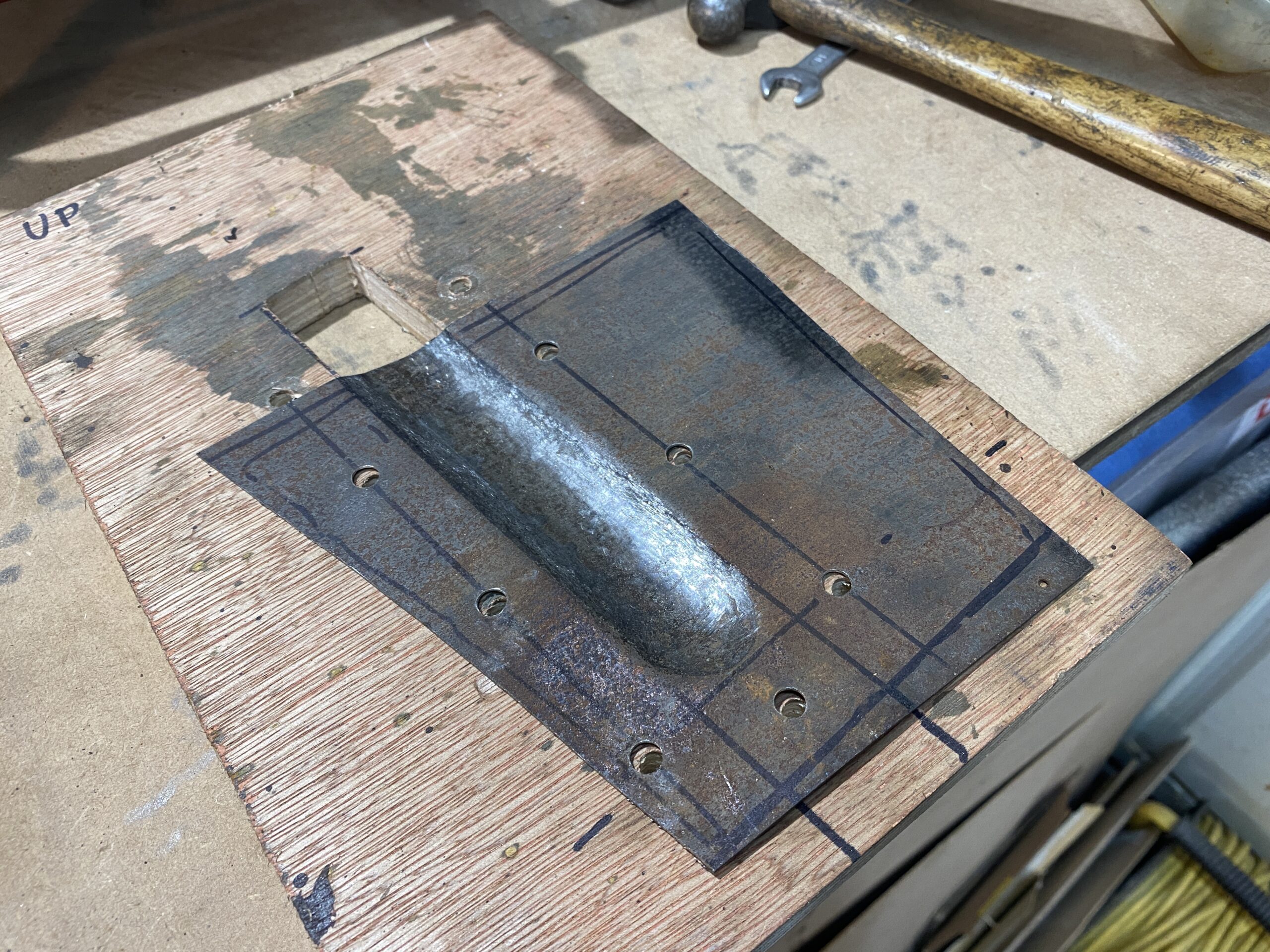
In Part 1, I made a paper template for the repair patch and that repair patch needed a strengthening bead included in the fabrication. Naturally I do not have a beading machine so I will have to make that beading by hand. YouTube came to the rescue as usual and I learned how to make a tool for creating that bead (indentation), which was basically 2 pieces of plywood with the beading shape cutout. The metal panel is then sandwiched between the pieces of wood, clamped down hard and then a ball pain hammer is used to beat the shape 'through' the cutouts of the wood. The metal plate cannot go anywhere so where the metal is not supported, it will bend with the force of the hammer - which in this case means the metal will deform into the shape I want. Naturally this is easier said than done and it took a lot of hammering to create a smooth shape.

This is the wood former: 

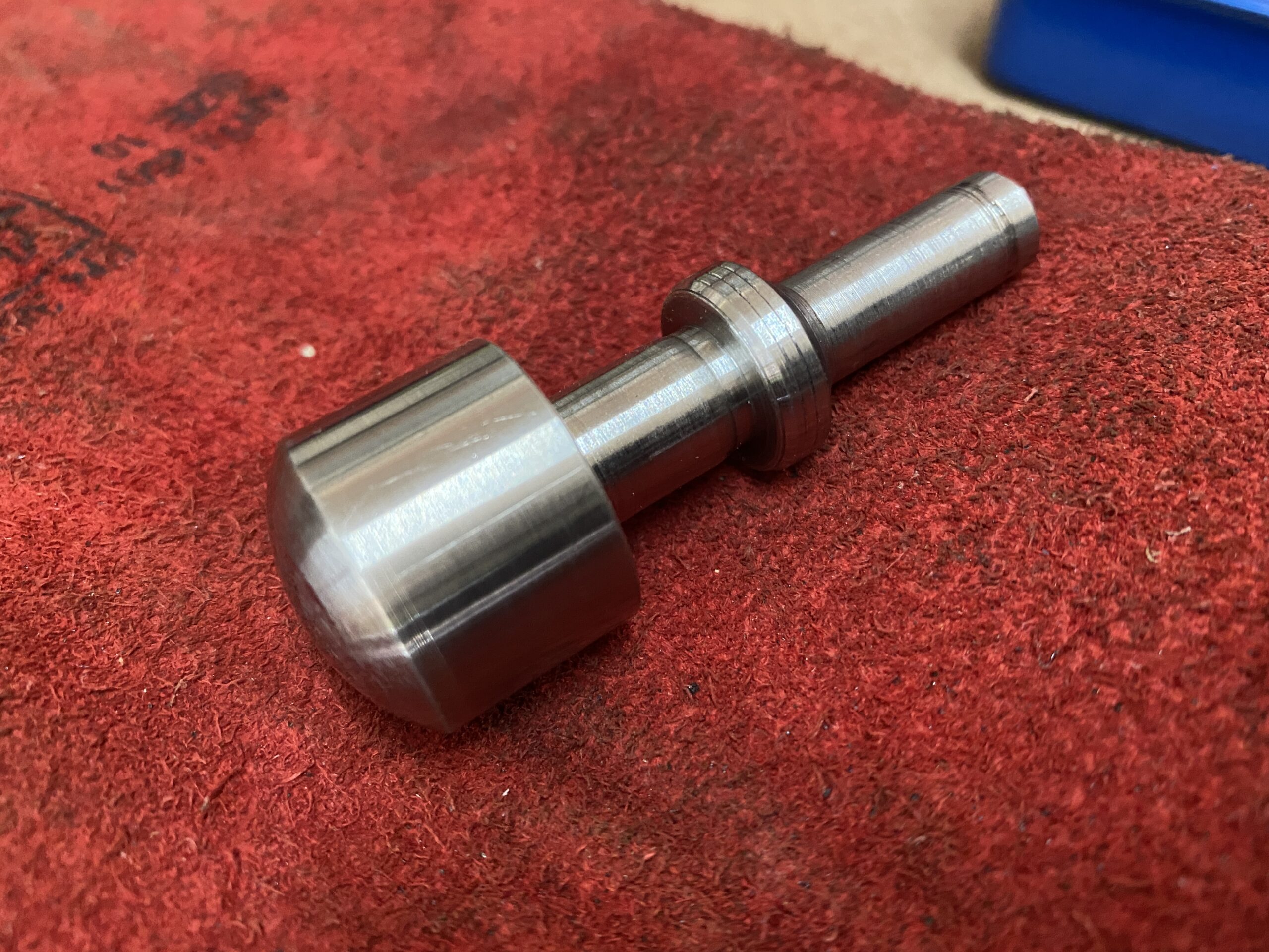
You basically hammer the metal you can see sandwiched between the wood. This takes quite a lot of time to obtain a smooth finish, so I figured I would make a perfectly shaped tool for my air hammer which hits 1000 times a minute. I had some 25mm stainless steel bar and so decided to make an air hammer bit from that. I think this was a mistake because I had never machined stainless steel before and it took me quite a while to work out how to machine it on the lather - the problem being that the metal work hardens very quickly and then CANT be machined - so it took a few attempts before I worked out how but in the end (after many hours) I created the hammer bit below which is the perfect size and profile of the beading in the panel.

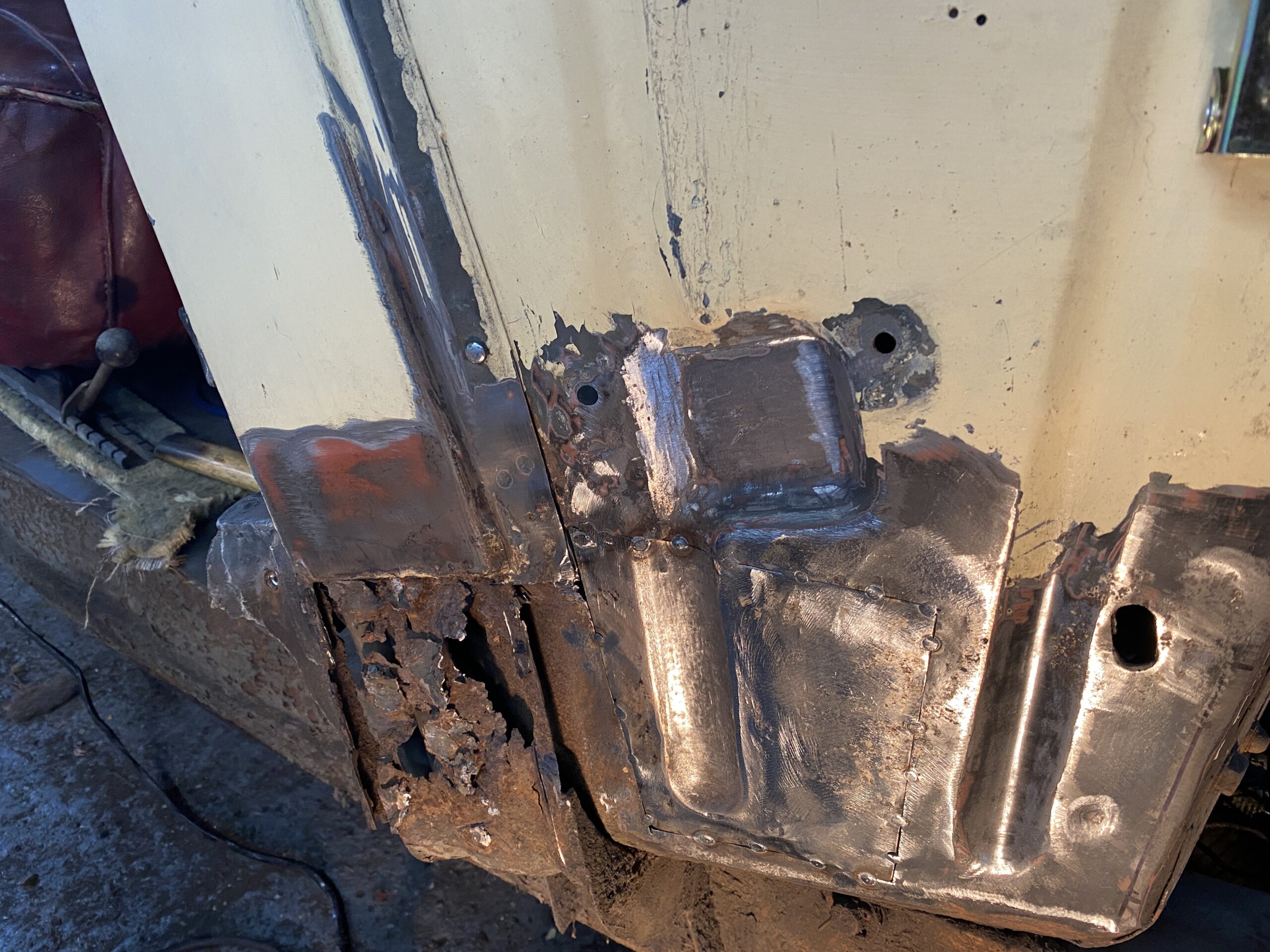
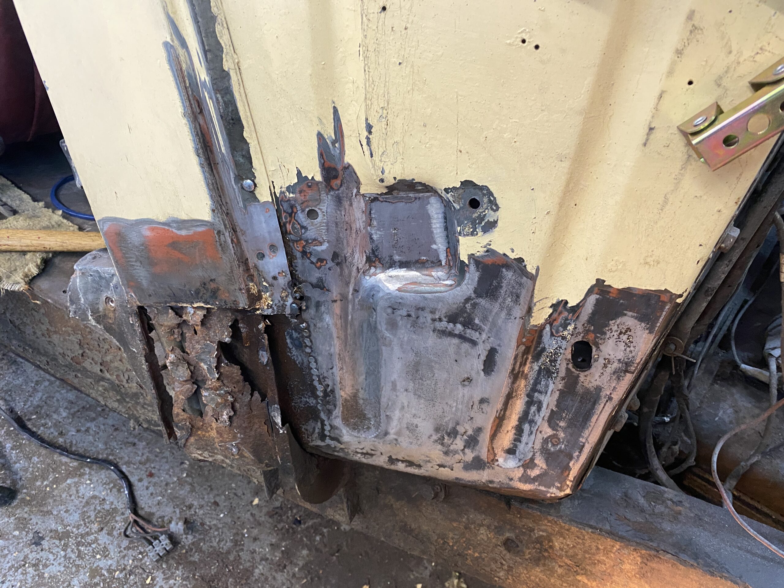
Hammering 1000 times a minute is not surprisingly much faster than hammering by hand and I soon had a shaped patch panel that I could trial fit. Below are a few pictures of the newly shaped patch panel, the trial fitting into the car , the initial tack welds and finally the almost finished panel which now just needs a little panel beating to remove the low spots revealed by sanding. To be fair this panel will be below the front wing and out of site but that doesnt mean that I shouldn't do my best to restore it.


I am quite happy with the (almost) end result - when it comes to painting to the car, I will put a thin layer of lead over the repair which will then be flatted back to achieve a nice finish, which will then be covered in a protective coating of under seal but as I say, whether you can see repaired area or not is not really the point

Metalwork Part 2 – Drivers Footwell

Metalwork Part 1 – drivers footwell

Where to start? Always a hard question when you commence a restoration and this car needs so much work. I imagine I will jump from one thing to another as my mood takes me but initially I have decided that because I do not yet have sufficient spare cash to rebuild any of the mechanics, then perhaps I should start with something that only costs my time - the bodywork. There is a lot needed. The lower section of almost all of the lower 300mm or so of the car bodywork is corroded to a degree. The chassis seems to be fine and once it has been degreased and the rust scale removed, that will only need a good protective coating before it is usable.

I have decided to start with restoring the drivers footwell. More specifically the external panel that is beside the accelerator pedal. Part of this panel is visible when the bonnet is open and part of it is hidden below the front wing. In the case of my car there is a weird set of ripples next to the rear bonnet lock but I know that part of the panel should be flat. The bonnet securing plate also seems to have been pushed in towards the drivers feet but I cant imagine how that damage occurred.

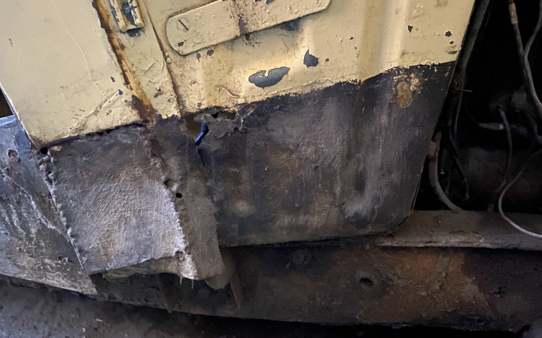
Its not too easy to see in the picture above, but there are two strengthening shape in the panel. The one on the right hand side is pretty well defined, a little miss-shapen, but easily returned to normal. The same indented shape is supposed to be there on the left hand side and it runs up from the bottom of the panel and under  the square shaped-impression beneath the horizontal bracket you can see towards the top of the picture. I agree - you can barely see that vertical strengthening - the panel is too miss shaped. You can also see a small rusted hole where the black undersea meets the cream coloured paint, and next to that on the left is an old repair that I will replace because it doesnt look very nice and it may well be hiding some more rust. All of this area is the front mounting for where the bodywork is bolted to the chassis. I therefore want to restore this section and make it strong again before moving onto the panels that the wings are bolted onto and the door closes upon.

Step 1 - removing that old repair.

I am glad I did... that repair was hiding the original metal that had rusted through and beneath that rusty metal is the strengthening panel work that runs up through the whole door post. The bodywork in this area is what bolts the bodywork to the chassis. Granted none of the bodywork is structural but this is a body mount and a lot of strength has gone. So the layers of rusty panels will each have to be cut out and replaced with healthy metal, each layer adding back the missing strength. Luckily my new Jaguar Forum friends have supplied me with a plethora of photos of what this area is supposed to look like. So the metal work begins.

One thing at a time though.

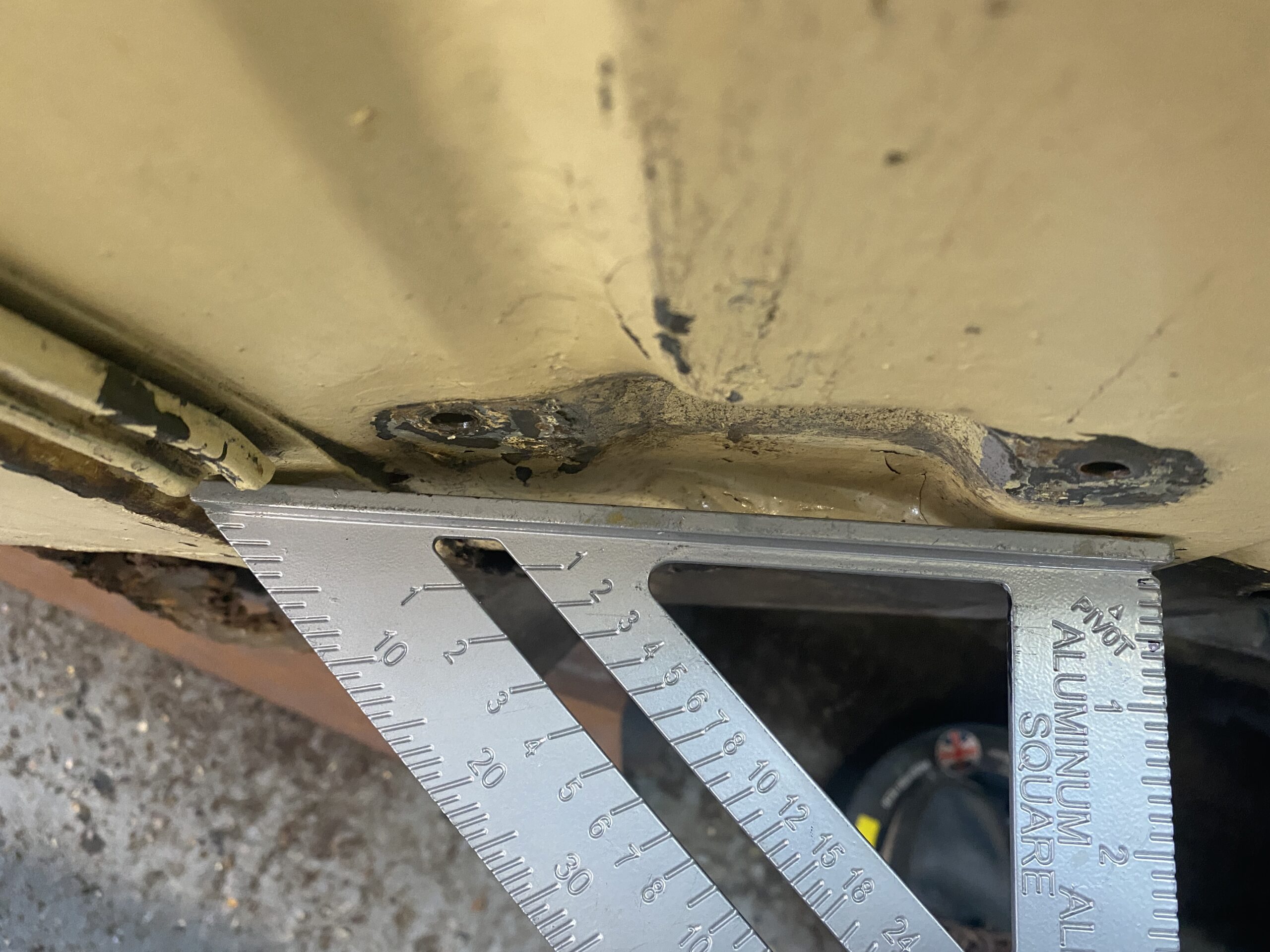
First I need to correct the area where that horizontal bracket has been pushed in otherwise I will be welding good metal onto damaged metal.  In the picture below, I have removed the bonnet securing bracket and have placed a straight edge onto the panel. You can see how much it has been pushed in, you can also above the bracket area - the strengthening indentation that I was trying to describe earlier (that runs all the way to the bottom of the panel). I would say that this area has been pushed towards the interior of the car about 1cm - but how to pull it back... A small slide hammer just made a lot of noise and the panel is too thick and strong for a panel beating hammer so something stronger is needed.

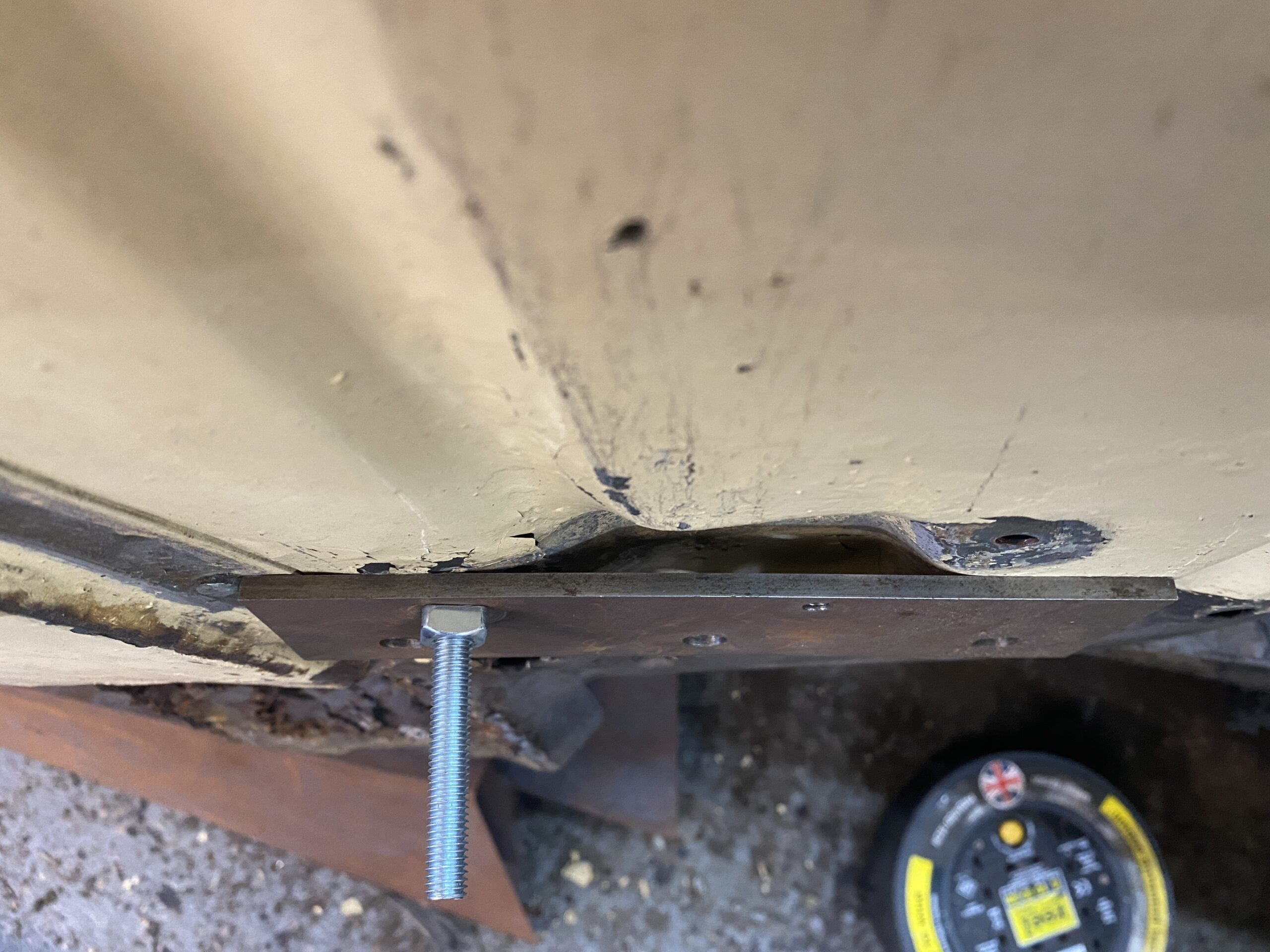
My answer was to create a 'puller' whereby a bolt was fitted through the handy bracket mounting hole and inserted into a 5mm thick steel plate. Tightening a nut onto that suitably braced plate - literally pulled the metal back into shape which would then allow me to do a little panel beating onto the remaining distorted area which I discovered was distorted because of rust.

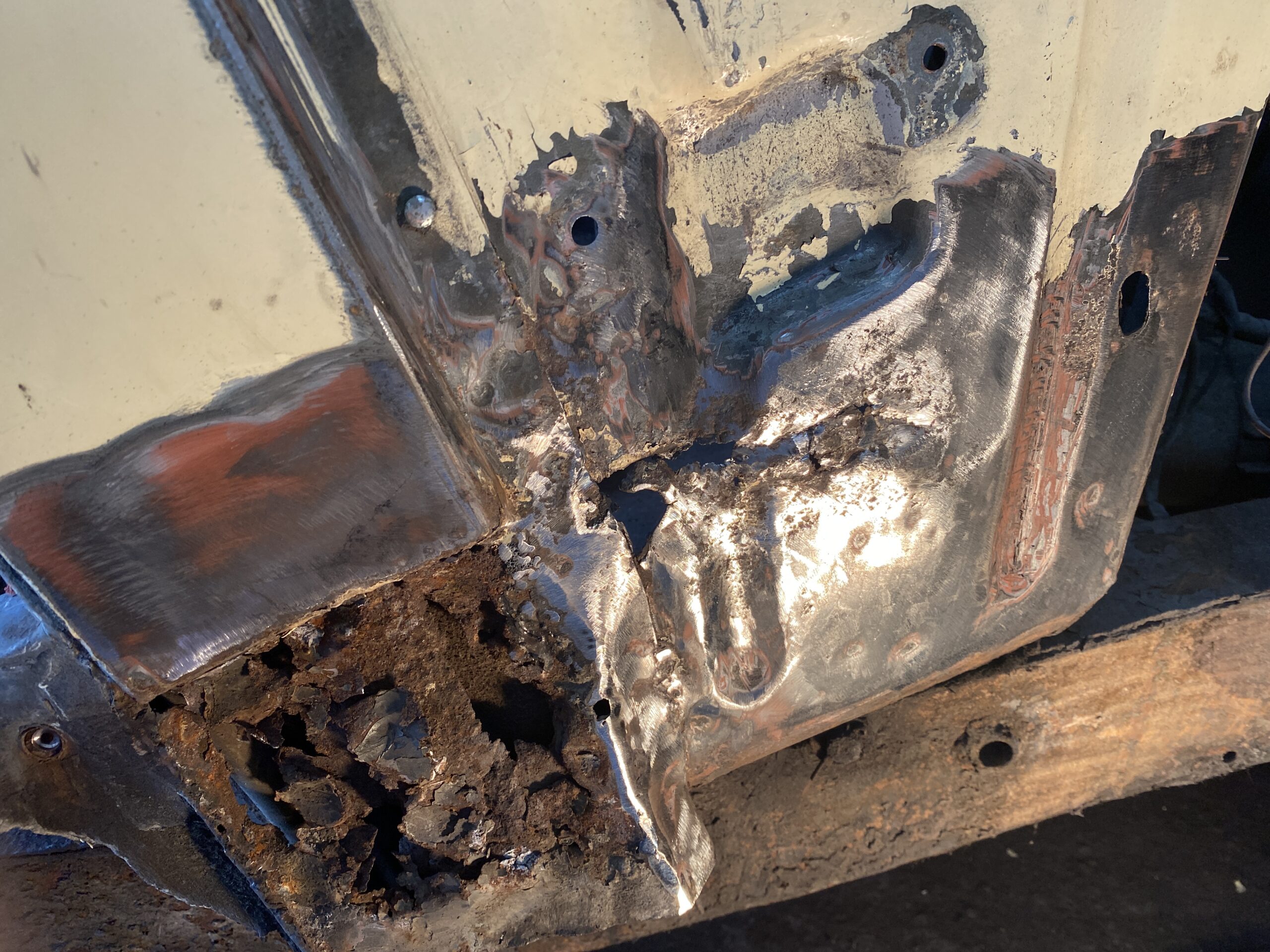
Above you can see the reason the panel was distorted - there is a line of rust running horizontally across the strengthening indentation. So I think the only answer is to cut all of that out and make a repair panel which will have to include that semi-circular strengthening indentation as well. That's a fabrication challenge in itself but I think I know how I can do it - off to the computer for some YouTube instruction...

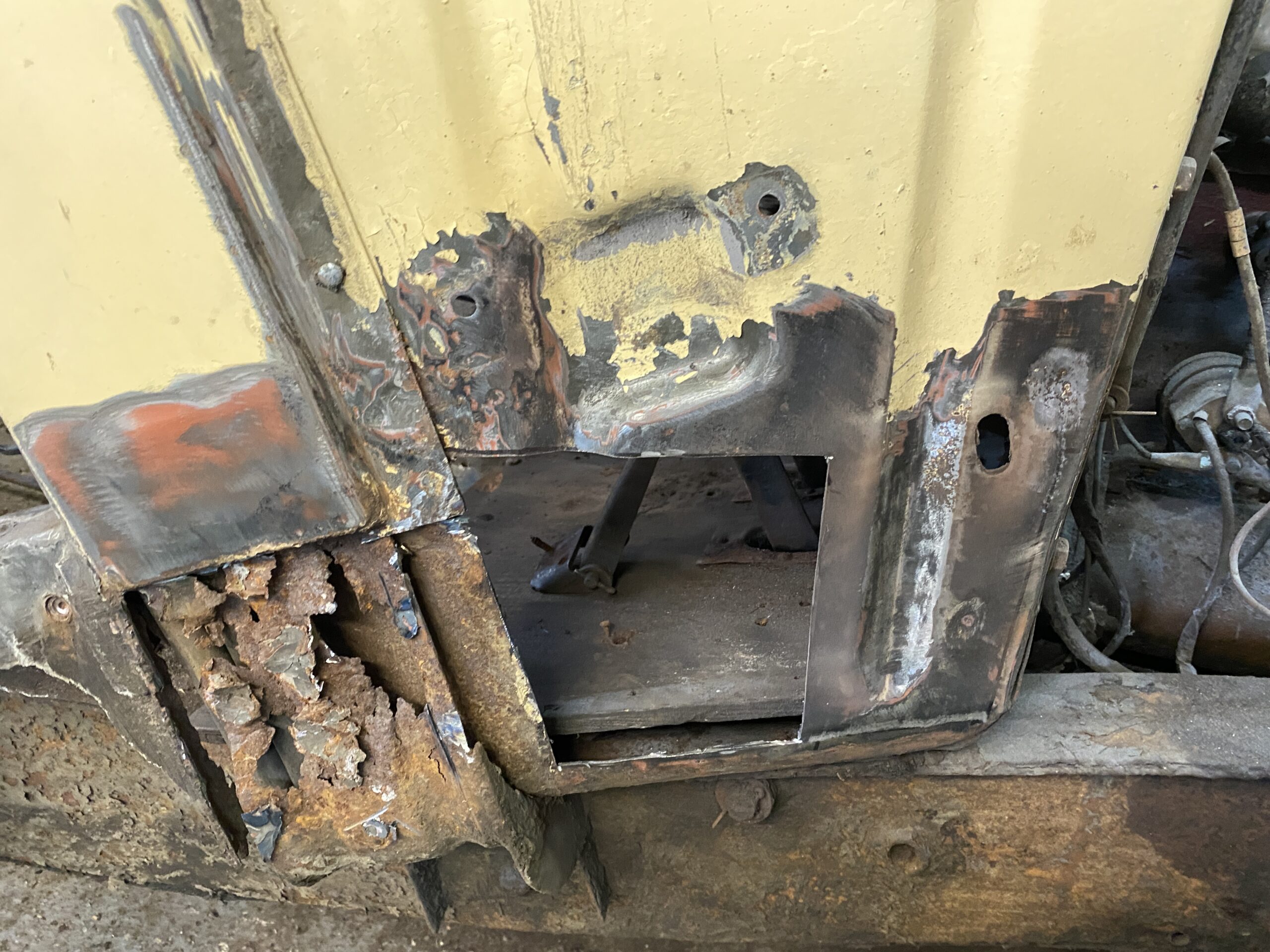
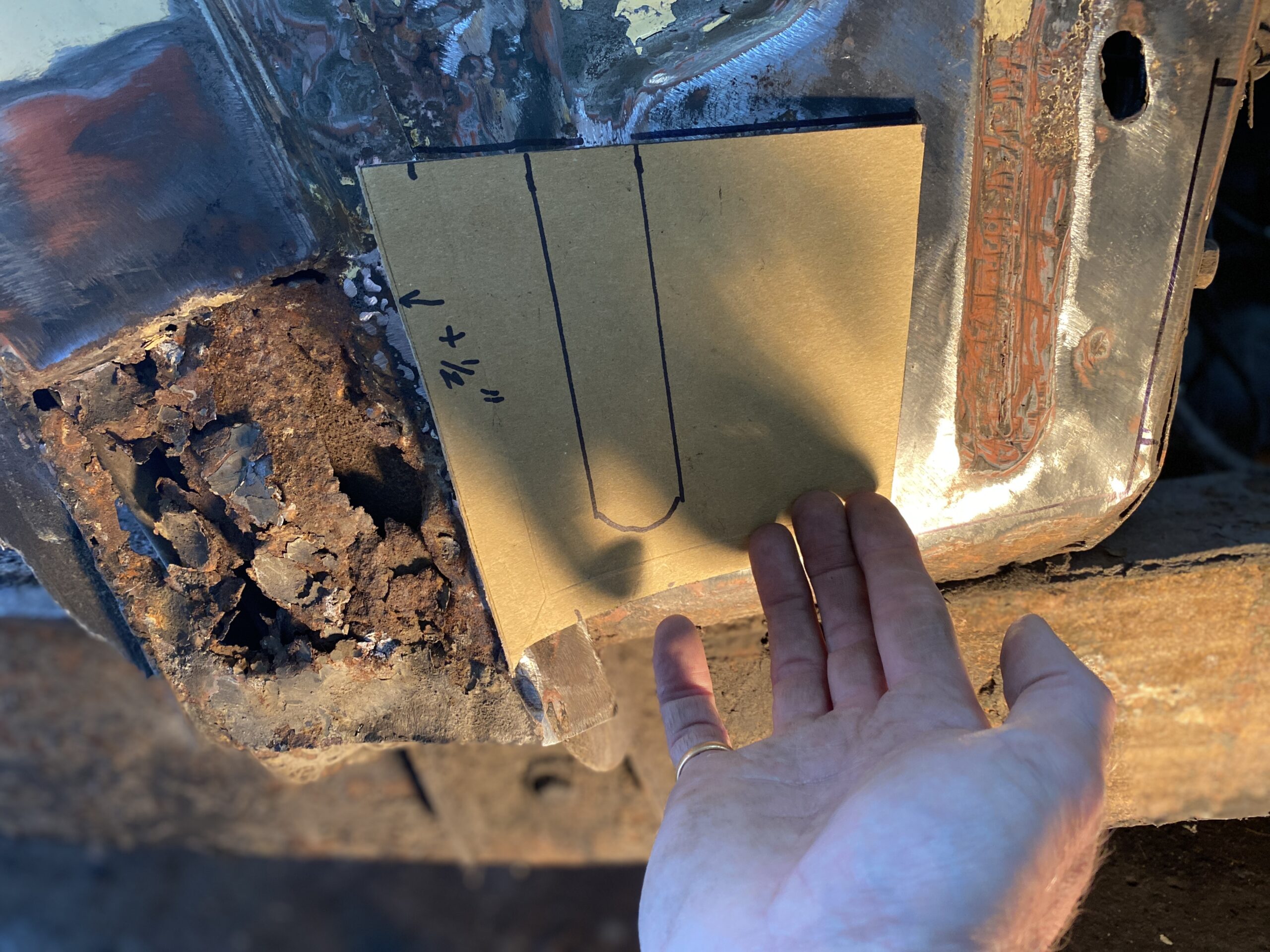
Okay time passes and I am back. Yes I now know how to do it, it will just take time, but first I need to remove the damaged areas and make a cardboard template. 

Yep that should do it... back in a week or so once I have fabricated the repair panel...

Seat Rebuild Part 3

Seat Rebuild Part 3

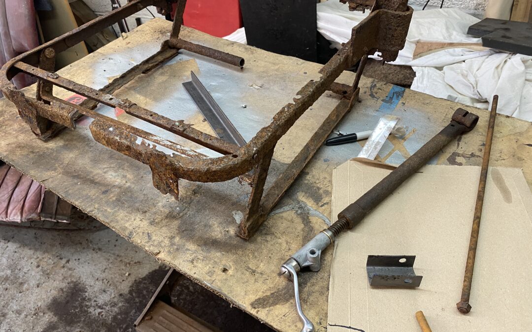
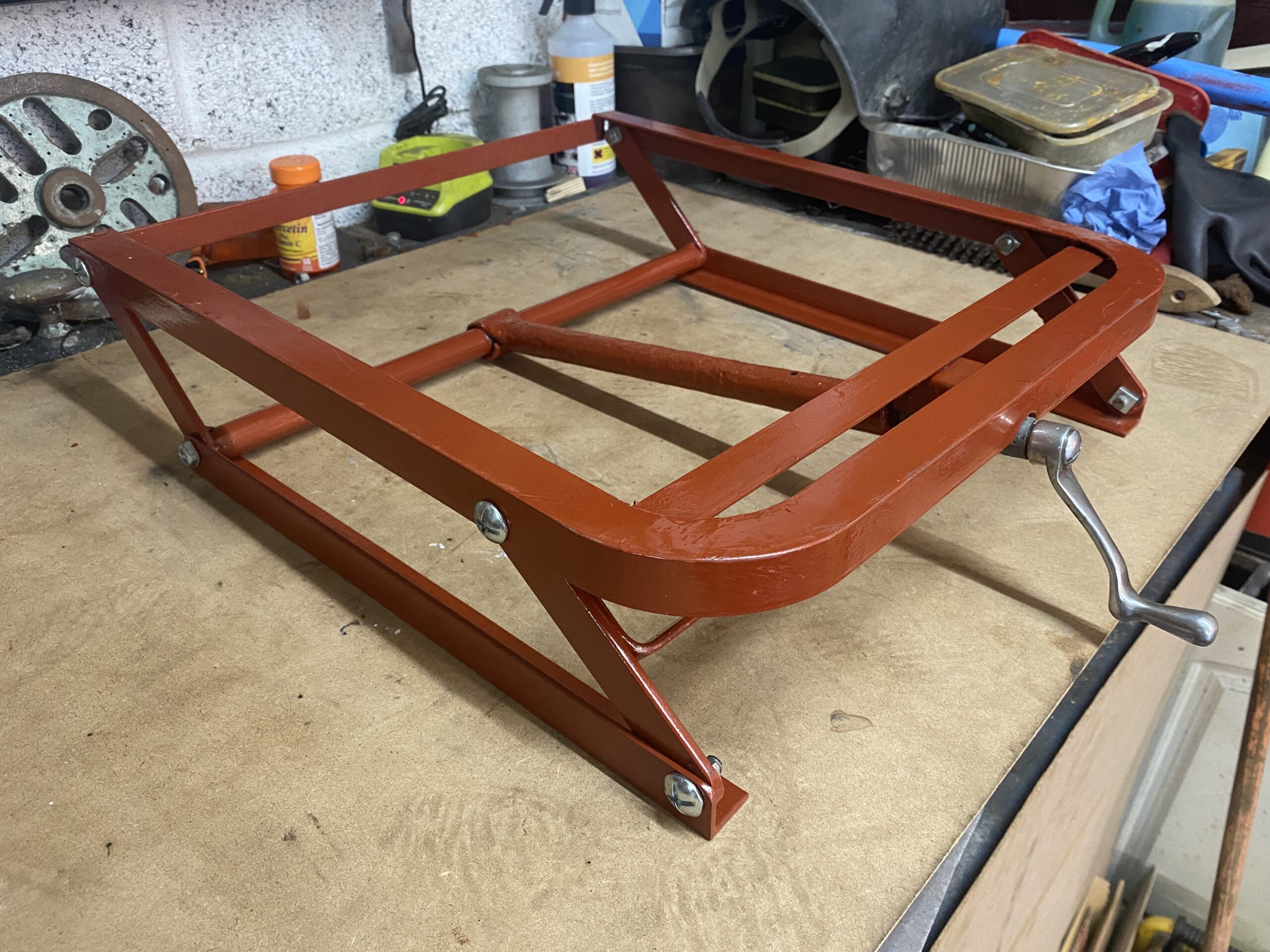
The construction continues. Using the technique for bending angle iron that I identified before, it was time to get-on-with-it. So I fabricated the top of the seat frame out of one piece of 3mm thick, 25mm angle iron. It looks like the factory used 20x25mm angle but I cant find that in the shops and no-one other than the trimmer, will ever see it anyway. The top of the frame  sits on a carriage which has a lovely chrome handle on teh front of the seat. That handle when rotated moves the seat up and  forward or down and backwards depending on the direction of movement. Having freed and partially rebuilt the handle mechanism, I was quite keen to maintain this feature and looking at the frame it was pretty easy to understand how it worked and it looked fairly easy to fabricate too. It was just more angle iron and 5mmx25mm flatbar with a bunch of holes drilled in the right place and some welding.

At the bottom rear of the frame, there is a tube with an 8mm bar running through it that the winder mechanism uses to push the top part of the frame forwards, so it needs to be reasonable strong and the ends of the tube are welded to two pieces of flat bar. It is all pretty basic, I just need to be careful when measuring each component to ensure that they are the same length and the hole positions are equal else the frame will twist. The seat back frame will be bolted to the top of the seat frame and I can see that the manufacturer added a couple of. substantial brackets to support the seat back. Luckily after several hours of soaking in de-rust liquid - I managed to save those brackets so they can be used again.

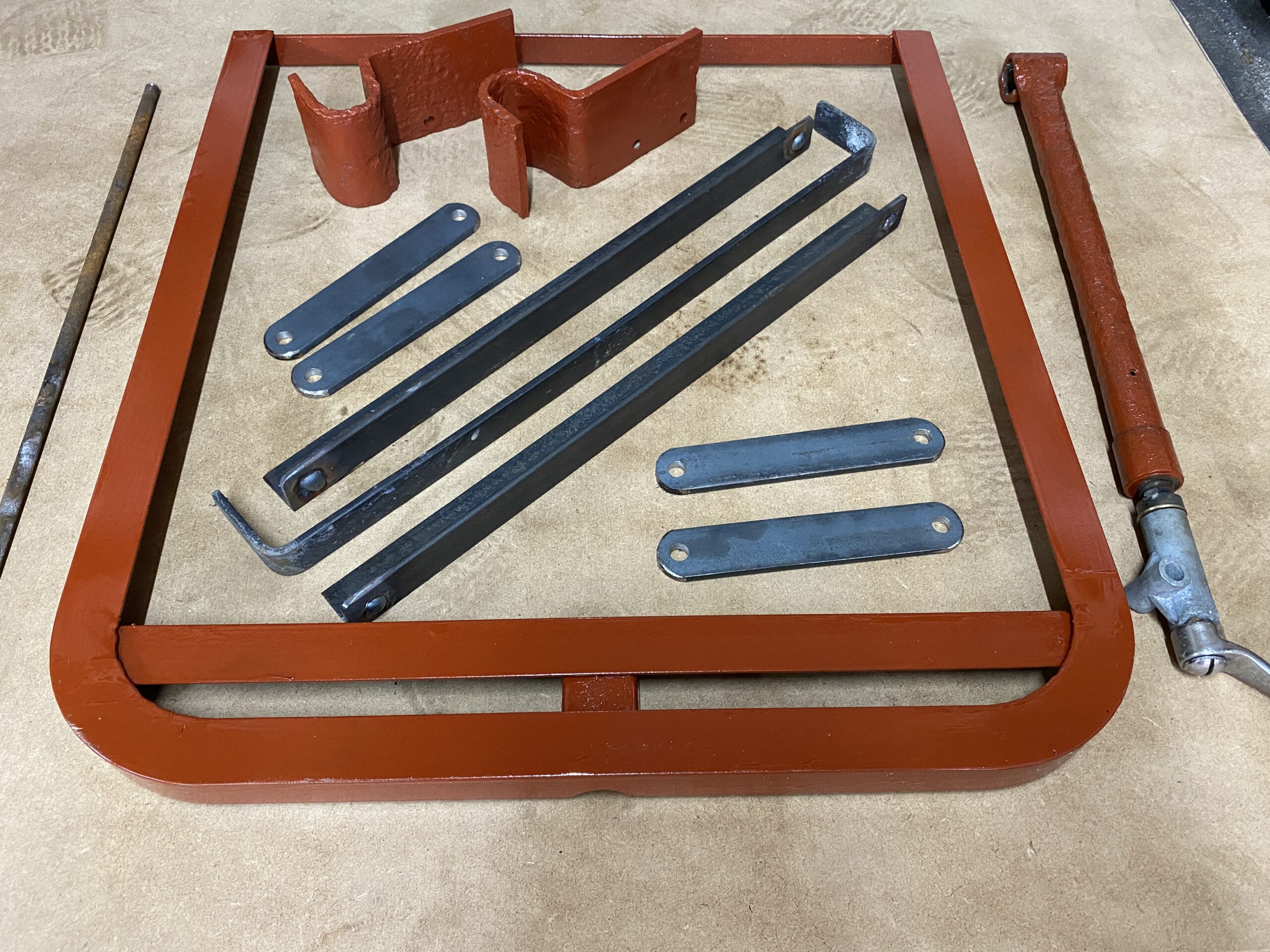
Below is the seat top frame and the fabricated components: you can see the winder mechanism on the right.

The ripples you can see in the Zinc primered frame are actually an excess of paint, rather than un-smoothed welding. I then carefully measured and drilled the seat top frame so that in the maximum upright position, every short flatbar would be vertical (which looking at the good drivers seat is how it is supposed to be.

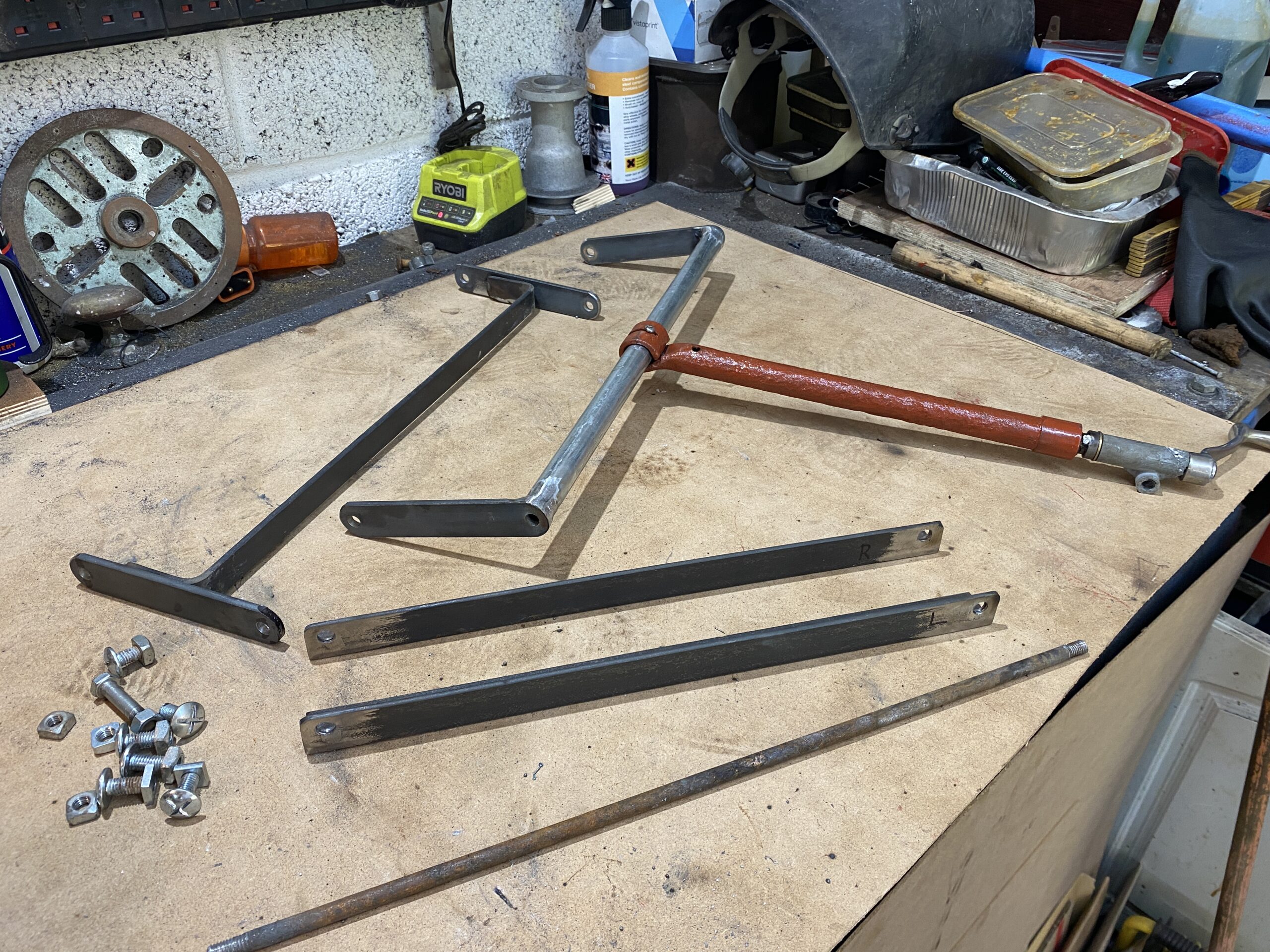
Below you can see the various components that needed to be welded together.

All it took then was to cut some 8mm fixings to a uniform length, cut and thread a new bar for the lower rear of the frame, make a new retaining bar for the handle mount and fit some nuts. Trial fit completed successfully, it now all comes apart for coating with Zinc primer

Next comes the part that I am not yet sure how to best achieve: Bending 22mm pipe into a series of smooth flowing curves like the original frame. I have a few ideas but which one will work. I have some electricians conduit to play with but the final version needs to be thicker walled for strength.

First Wash for many years

First Wash for many years

Working on dirty cars is not as nice as working on clean ones. Clearing off years of grease (some of it will date back to the 1940's) is a whole different ballgame but I will get to that at some point, but initially, I wanted to wash off all the dust from years of sitting in storage as that helps me get closer to knowing every inch of the car and to be honest the significant amounts of dust will not bring any benefits to breathing - so I pushed the car out onto the drive and went to collect some cleaning materials. Naturally, at that point, the restoration god decided to have a laugh and made it rain...

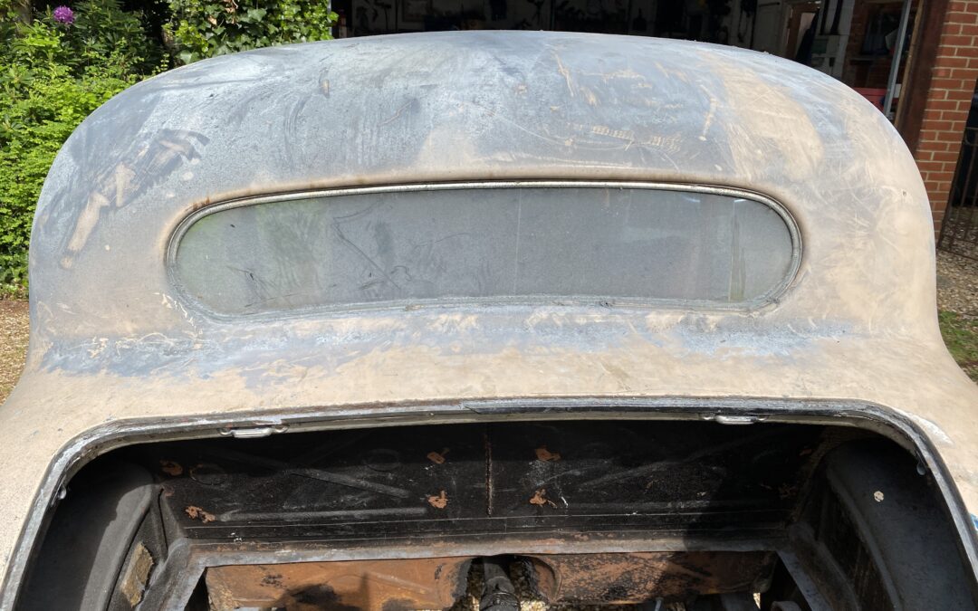
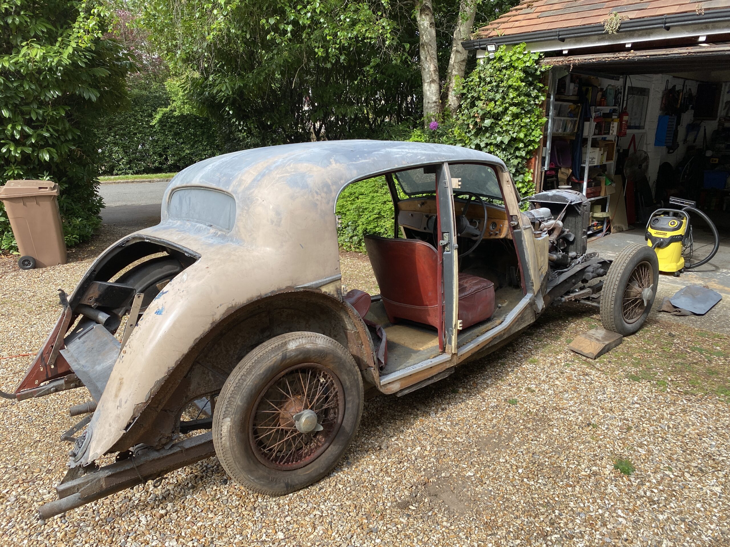
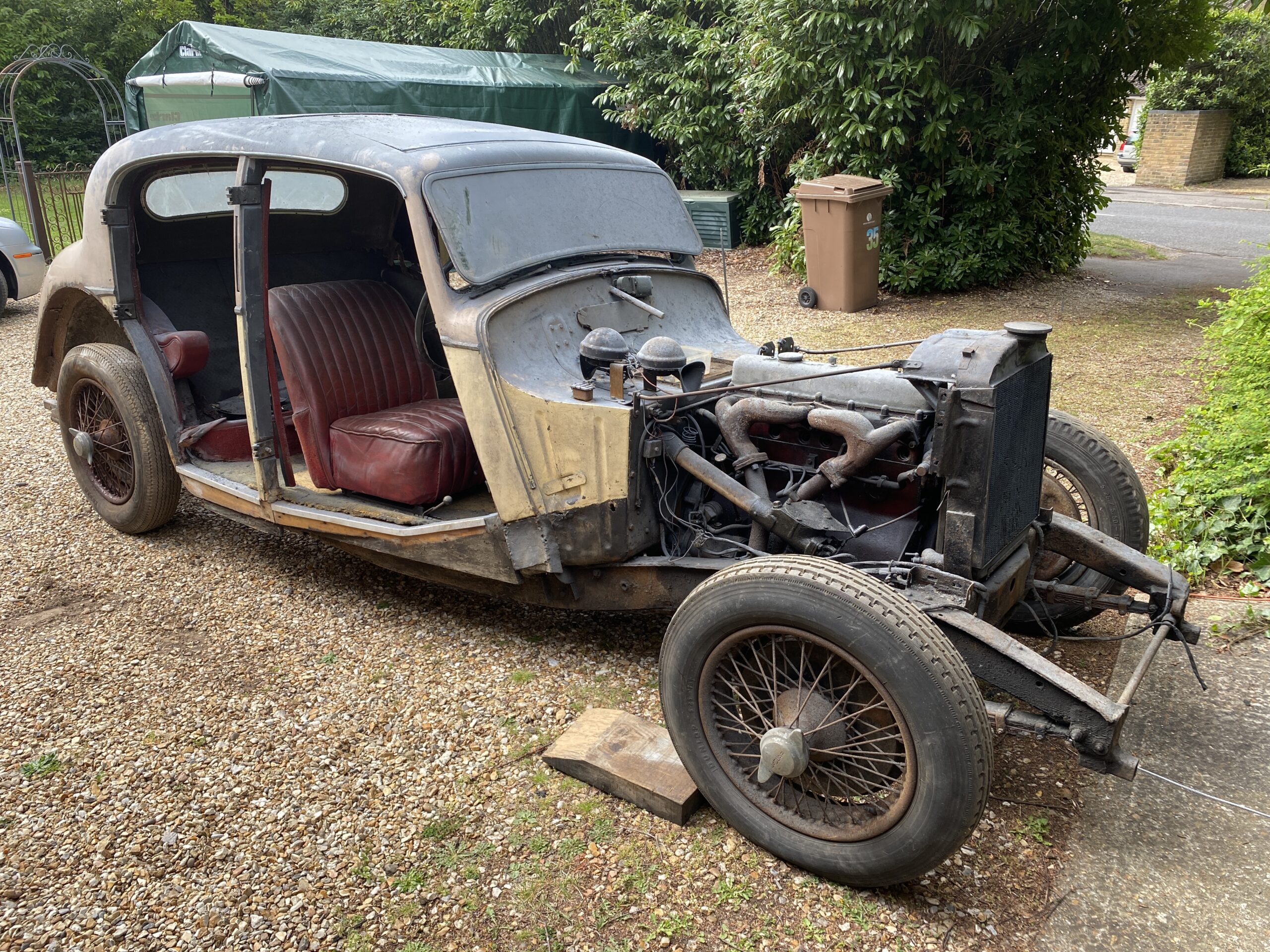
I was not to be put off though, the gentle rain would deposit a constant flow of clean water onto the car which I could use to rinse off the worst of the grime and it didnt take too long to reveal the paint that Steve had applied by hand all those years ago. It looks very different now that it has been washed and hoovered out.

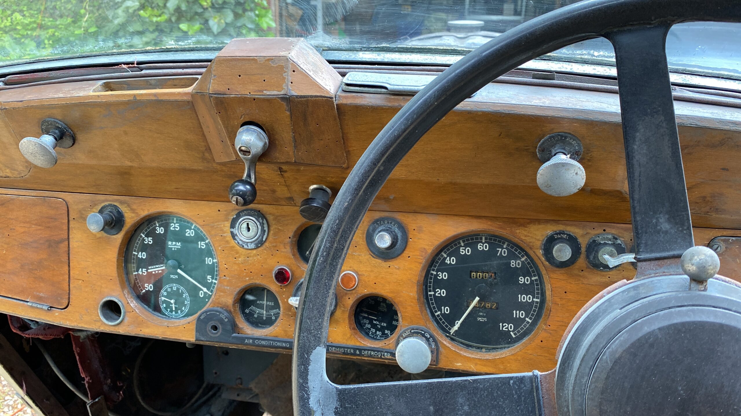
You can actually see through the windscreen and rear window glass. I also gently wiped down the instrument panel and the drivers seat (the only one still in the car) and it was at this point, sitting in the car, that I began to really fall in love with the car - thoughts of sitting there surrounded by acres of polished walnut and leather whilst rolling along through the countryside with my beautiful (and very understanding wife) began to creep into my mind. The instrument panel and all those old gauges are lovely, this was a quality car back in its day and it shows.

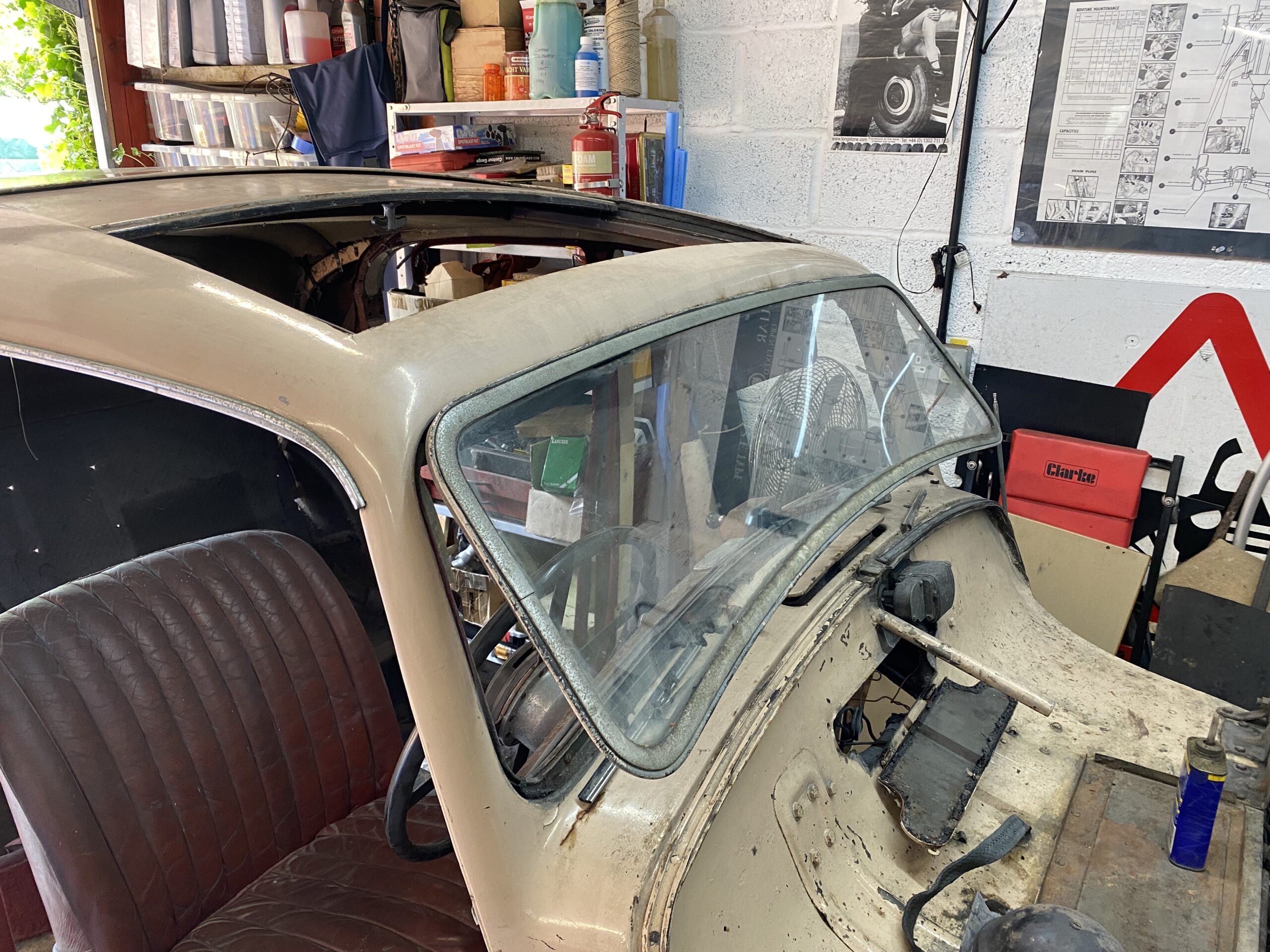
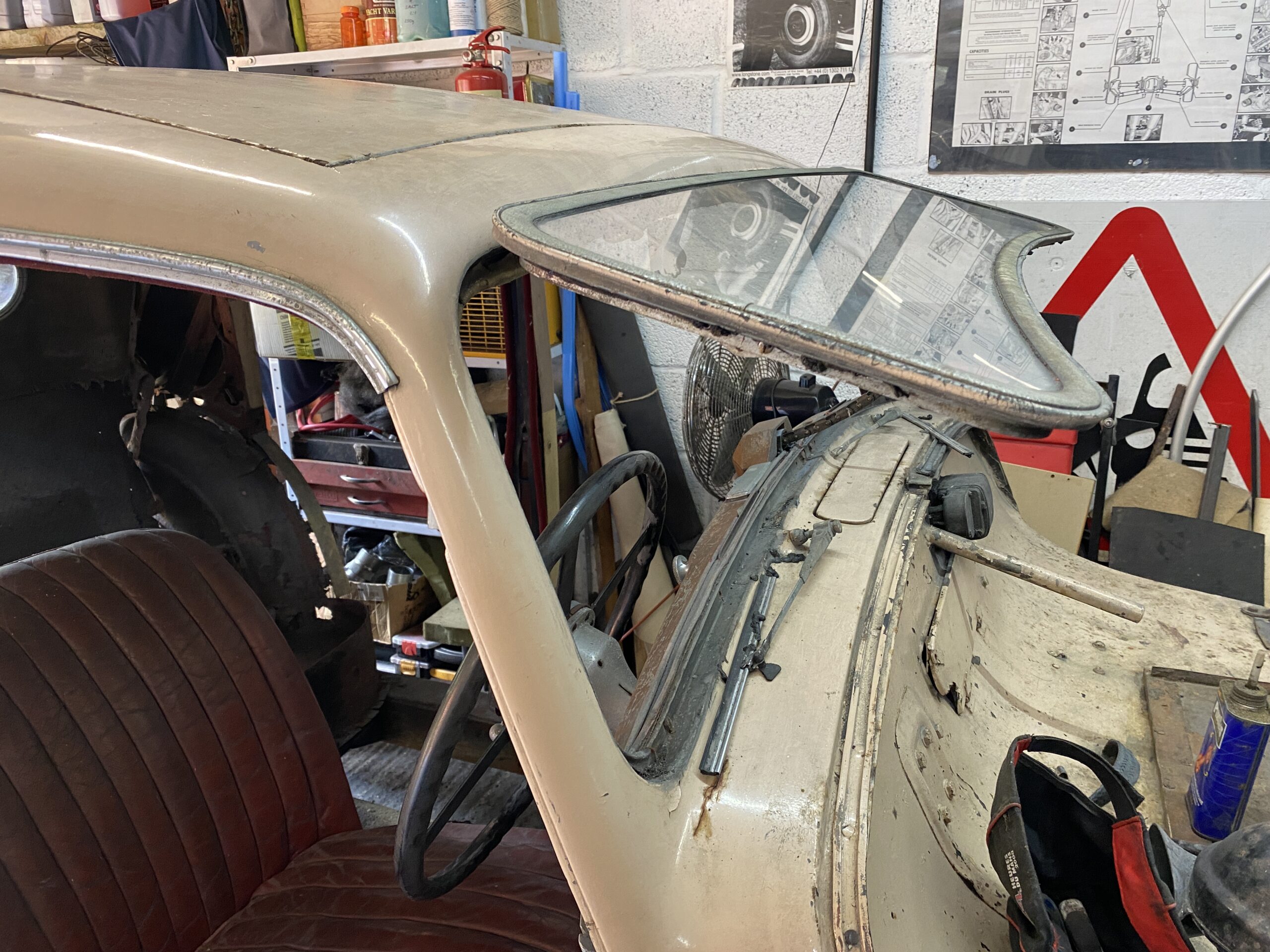
One of the features of these old cars is that the windscreen opens up by turning a cute little handle at the top of the instrument panel. I wonder... yes the handle turned albeit reluctantly, but with some gentle back and forth movement I could see the windscreen moving so continued with slowly increasing the movement until the handle rotated fully and I could put some releasing fluid on the mechanism and on the hinges. Some more gentle easing and the handle rotates freely and the window opens up just like it should - to almost horizontal. I bet that lets some air in...

I then turned my attention to the sun roof and similarly with a little gentle persuasion that too opened fully and be greasing the runners it slid back and forth quite freely. It doesn't fully shut because the sealing rubber has gone hard but making the sliding roof function nicely is a job for another day. Both of these niceties are not really where you should start a restoration but it is nice for a feel good factor.

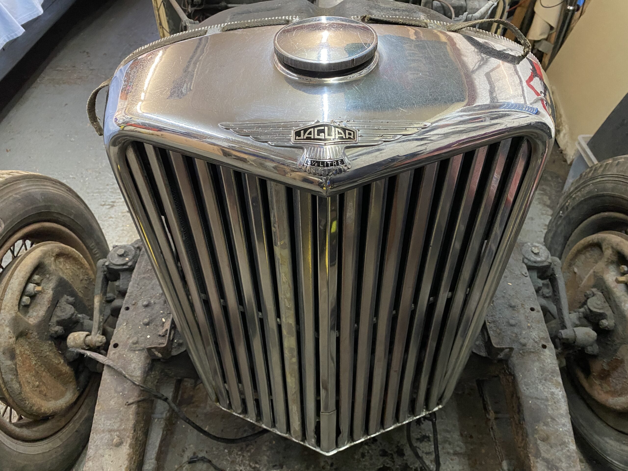
I have previously used 'de-oxidising' spray on aluminium as a quick way to remove the dust like coating that appears after a few years and is a great precursor to re-polishing aluminium so I wondered if it would also remove oxidisation on chrome and it certainly does! I first tried it a small area of the windscreen chrome. All it takes is a light spray and some mild agitation with a brush, then you leave it for a few minutes and wash it off. The difference was remarkable - WOW!

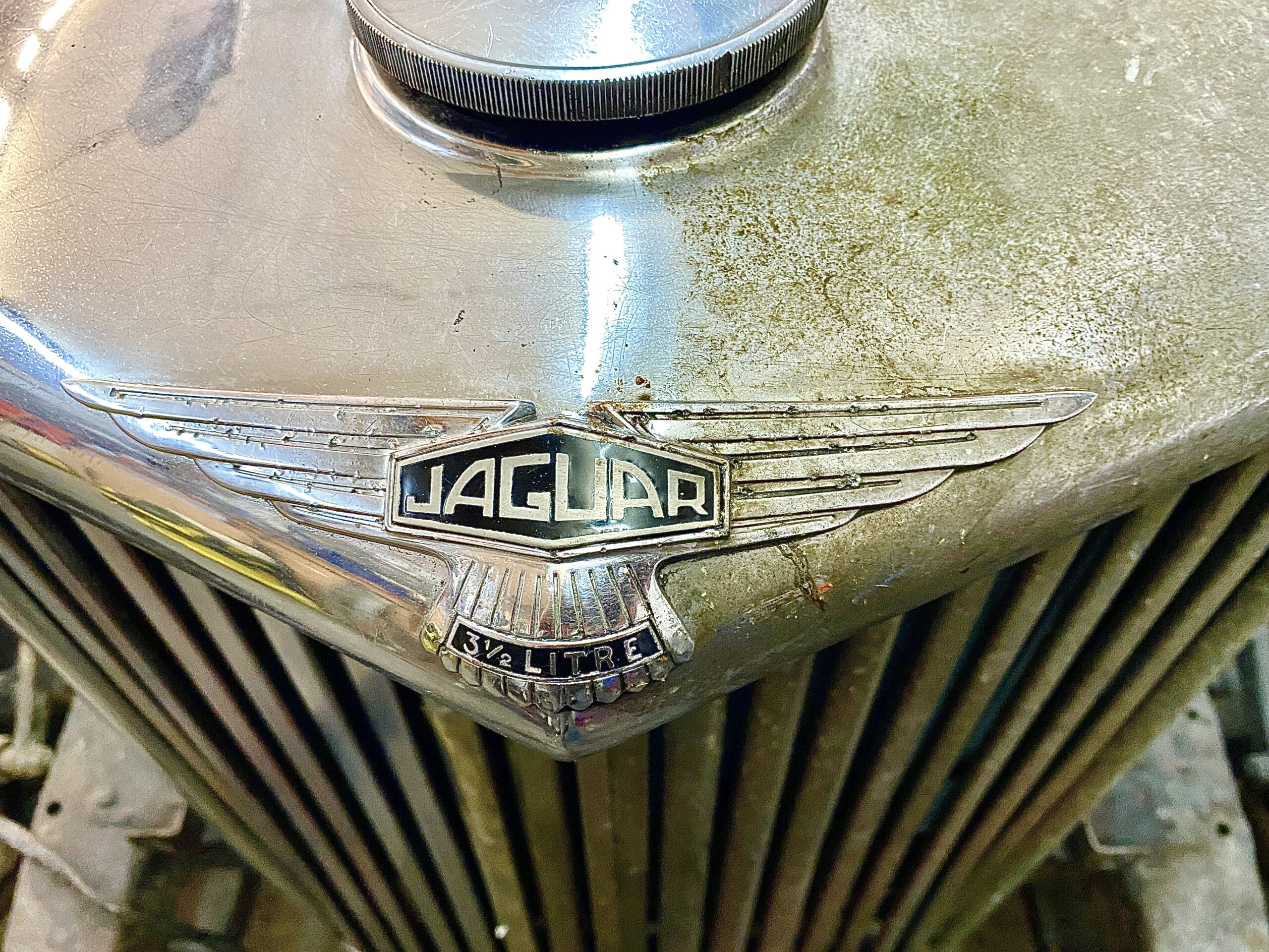
So I thought I would do a before and after on the radiator grill as that has a lot of chrome and I thought the chrome was probably beyond recovery... but you can see the difference in the photos. I have NOT polished the chrome at all - the difference is purely down to the de-oxidising fluid, polishing (not important right now) will bring it up nicely,  not good enough for a show car but quite acceptable as an interim for a car that is driven.

Click on any picture to see a larger version.